2
Overview of Streams and Methods
3
Technolithes and building material engineering
4
Mineral composition of technolithes
4.1 Mineral
composition of heatproof technolithes.
6.1.1
Products of devitrification
6.1.5
Occlusion and devitrification
7.1 Mineral composition of used chamotte
7.1.1 Chamotte and linings of blast
furnaces
8.1 Magnezite
heatproof matters
8.1.4
Microscopy of used basic heatproof matters
9
Mullite and corundum matters - matters with high aluminium oxide content
9.1 Cast
and molten heatproof matters
9.1.1 Mullite-corundum products of
the „Corhart Standard“-type
10.1 Mineral composition of molten rocks
11
Mineral components of a high-temperature slag
11.1 Basic blast furnace slags
11.2 Acidic blast furnace slags
12
Siliciumcarbide and grafite matters
12.1.1 The mineral composition of
the siliciumcarbide matters
14.1 Portland cement clinker..
14.2.1 Methods of identification
14.3 Mineral composition of air mortars and plasters
14.4 Mineral composition of hydraulic mortars, plasters and concretes
16.5 Porcelains not containing glass - oxide ceramics
Miroslava
GREGEROVÁ,
Ústav
geologických věd, Přírodovědecká fakulta MU v Brně, Kotlářská 2, 61137 Brno, mirka@sci.muni.cz
Key
words:
Technolithology, technolithe, microstructure, microstructure, building material
engineering
Mineralogical
and petrographical systems have been recently facing a serious schism. Official
institutions try to exclude minerals and rocks affected by human activity while
experts attempt to define methods for practical issues in the branch. The
scenario relies on rather obsolete anthropocentric point of view without
concerning the fact that man has been an integral part of nature and has been
even more and more affecting all natural systems. If we accept this thesis also
for the mineral/rock system, there is no more disputes. There are three main
streams in mineralogy and petrology:
lithology -
natural minerals/rocks with development unaffected by human activity;
biolithology
- minerals/rocks developed by life activities of organisms including man;
technolithology
- minerals/rocks (technolithes) that have developed artificially or
intentionally in tight connection to human activity.
Technolithology
is an interdisciplinary geo-technical scientific discipline. Position of
technolithology in the earth material cycle scheme (technolithes, natural
minerals/rocks) may be demonstrated using simple illustration adapted from
Cohen (1980)-see Figure 2. The illustration shows that mineralogy and
petrography play significant role in the material engineering branch (building
engineering, respectively). Applied mineralogy and petrography include
mineralogical and petrographical study of materials with respect to their
potential application (raw materials). On the other hand, technolithology
focuses on research of synthetic products resulting from technological
transformation of natural materials. The study comprises microstructure,
mineral/amorphous phases, chemical composition, and physical properties. It
examines both quantity/quality changes during the technological processes and
stability/degradation under specific load conditions.
Hornbogen
(1983) was one of the first who recognized significance of
microstructures/microstructures for rapidly developing material engineering
branch. His assumptions have been based on historical aspects. He summarized
practical properties of natural materials (for example, rocks, copper,
meteoritic iron), well known procedures and technologies (for example, bronze,
steel, raw iron, cast iron, ceramics, glass, concrete), applications of
scientific procedures in up-to-date technologies (trace ingredients of Al, Ti,
Mg, metal alloys, ferrites and others), and special studies resulting in
development of Ni superalloys, Si3N4 ceramics, Al2O3-ZrO2,
components, semiconductors/superconductors.
Figure 3
shows categories of geochemical, mineralogical, and petrographical research in
technolithology including terminology used in material engineering.
In the
technolithe mineral group, it is possible to determine mineral classess that correspond
to those of natural rock minerals. As the technolithe composition always
depends on composition of original blends and technological processes used, the
mineral associations have been usually registered based on individual
technolithe groups (see Table 1).

Figure 1 Position of technolithology and earth materials' cycle (adapted from Cohen, 1980)
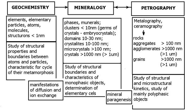
Figure 2 Objects of study (geochemistry, mineralogy, and petrography) applied in material engineering (Szymañski 1997). Legend: structrone-basic microstructure polyhedron, cluster-embryonal crystal is a embryonic cluster of crystals that is not identifiable using roentgenography, domain-major microstructure element with poor X-ray diffraction, crystallite-microfragment of crystal patrice with distinct X-ray diffraction, aggregate-compact, non-porous particle consisting of crystallite, agglomerate-porous particle consisting of aggregates or crystallites, braun-non-regular particle of minerals or phases.
Table 1 Overview of common fireproof technolithes including composition and application temperature (Gregerová, 2000).
|
Fireproof
technolithes |
Mineral composition
of original raw material |
Mineral
composition of technolithe |
Main
oxides |
Application
|
|
Lime
silica |
quartzite,
chert + up to 5% CaO |
cristobalite,
tridymite, wollastonite |
over 90%
SiO2 below 5% CaO |
up to
1710oC |
|
Quartz
glass |
vein
quartz |
amorphous
SiO2 |
over 99%
SiO2 |
up to
1710oC |
|
Silica
chamote |
kaolin,
claystone, clay, silicarenite |
mullite,
cristobalite tridymite, quartz |
10-30% Al2O3
|
up to
1670oC |
|
Fire clay
|
fireproof
clays, claystones |
mullite |
35-45% Al2O3
|
up to
1750oC |
|
Peraluminic
chamote |
fireproof
clays, claystones, Al hydroxides and oxides, Al2SiO5 minerals
|
mullite, cristobalite corundum |
45-60% Al2O3 60-75% Al2O3 over 75 % Al2O3 |
up to
1840oC up
to 1900oC
up to 1950oC |
|
Fireproof
mullite technolithes |
Al
hydroxides and oxides, sillimanite, andalusite, kyanite |
mullite,
cristobalite, corundum |
60-85% Al2O3
|
up to
1960oC |
|
Fireproof
corundum technolithes |
Al
hydroxides and oxides |
corundum,
mullite |
over
60-85% Al2O3 |
up to
1960oC |
|
Spinel
magnesite (magnesiochromite) |
cemented
magnesite magnesite -chromite + Fe2O3, SiO2,
Cr2O3 |
periclase,
periclas+spinel, spinel |
over 80%
MgO 30-70% MgO 10-30% Cr2O3 |
up to
1700oC |
|
Dolomite
with fixed lime |
dolomite |
calcium
silicites, periclase, CaO |
cca. 40%
CaO |
up to
1900oC |
|
Dolomite with
free lime (cements) |
dolomite,
limestone, diatomite, magnesite, hematite fireproof clay |
periclase,
wollastonite, cristobalite, dicalcium/tricalcium silicite |
cca 35%
MgO admixture of other oxides 15-25% |
up to
1780oC do 1900-2000oC |
|
Chromite |
chromite |
chromite |
over 80%
Cr2O3 |
up to
2000oC |
|
Carborundum |
carborundum
|
silicon
carbide |
up to 80%
C |
up to
2200oC |
Figure 3 Procedure for technolithe study
In 1981,
the International Council on Applied Mineralogy (ICAM) was established. The
council was initiated by a group of world's top mineralogists whose research
had concerned industry-based mineral eCPLoitation. The council was formed at the International
Mineralogical Association (IMA) conference held in Johannesburg. At congress
held in 1984 in Los Angeles, the ICAM was finally defined as an independent
organization coordinating its activities through IMA. ICEM's objectives include
organizing of international interdisciplinary activities and conferences. The
conferences enable sharing information between experts from various branches
somehow connected to mineral application (mineralogists, chemists, engineers,
metallurgists, ceramics producers, health protection experts, and medicine).
Applied
mineralogy
comprises study of morphology, inner microstructure, and physical/chemical
properties of minerals that enter the technogenesis process. Results of the study make it possible to
modify the technological process and control its progress. Qualified evaluation
of final technolithe contributes to innovation and/or new technology
development. It focuses on search for new raw materials in the solid industry
waste field (for example, light ash, power-producing hydrated sulphate of lime)
and production of synthetic minerals (for example, jewelry production,
abrasives, and so on).
Applied
mineralogy is very useful for anthrophogennous mineral study, biolithology, and
biomaterials/bio-mineralization (medical applications mainly).
Technolithology (technical material petrography) is
an interdisciplinary branch forming a bridge between material engineering and geology.
The technolithes are studied by geology (particularly mineralogy, petrology,
and geochemistry branches). It has been proved that by using common analytic
methods on technolithes, a whole new range of scientific research opens to the
community (material engineering including research of cement clinker,
lime/hydrated lime, concrete, mortars and plasters, and ceramics). Basic
research streams have been defined in some fields that might require geology
and its methods to solve specific problems and first issues have been
successfully addressed (Rovnaníková et
al. 1999, Gregerová 2000, 2000b, 2000a,
2000c, Gregerová et al. 2000,
Gregerová, Pospíšil 2000). Pattern-based relationships between stable,
metastable, and secondary minerals in building mortars and plasters materials
have been revealed using microscopic methods, RTG, DTA, and electron microscopy
(Gregerová 2000a, 2000c, Gregerová, Pospíšil 2000a, Gregerová, Rovnaníková
2002, Witzany et al. 2002).
It is
obvious that petrography with its experts has become significant, too.
Petrography is able to analyze both final products of various technological
processes and the actual development processes/technologies. The products can
be both mono-mineral and poly-mineral materials with variable chemical composition.
Their compositions (microstructures and microstructures) reflect different
kinetics of their genesis.
For rock
melting process study that has been performed since the end of the 19th
century, Huang (1962) used the term petrology while Ginsberg (1961) preferred
the term petrurgy. Intense development of microscopic methods and their
application to ory minerals resulted in a separate branch-metallography. Berry
and Mason (1959) stated that natural minerals included industry-applicable
minerals and industry-non-applicable minerals. Industry-applicable minerals
further included general minerals, rare minerals, and strategic minerals (the
ones required in electronics/weaponry development).
Requirements
for ceramic product shape/composition variability resulted in definition of a
separate branch entitled ceramography (Ryshkevitsch 1960). With growing
technology development, new technical streams of research have been defined
including material engineering. First laboratories of this type have been established
in the sixties in Philips company (Eindhoven), General Electric company
(Schenectadu), and Bell Telephone company (Murray Hill) (Kohl, 1977).
In
following period, the technical mineralogy branch has been experiencing both
vital and dynamic development. The development has been tightly connected to
boom of electronics as the materials used have been exposed to extreme
conditions. It was believed that only natural crystals (such as diamond,
corundum, quartz) could stand the conditions well. However, new technologies
succeeded in synthesis of new monocrystals/polycrystals with much better
characteristics. These include phototropic/photosensitive glass, optical
fibers, magnetic memories, monocrystalic layers, monocrystals used in lasers,
and so on.
As petrogenetic
studies combine various experimental/theoretic approaches with
inductive/deductive statements concerning rock genesis/development, they are
applicable all across the industry. The reverse approach is obvious as well.
Technological processes can be used to rock genesis detection. Up-to-date
technologies produce wide range of inorganic materials and artificial stones.
These have been described as "technical materials", "technical
rocks" or "technical matters" and studied by applied
petrography/mineralogy, technical petrography, technical mineralogy or
petrography of technical matters (Hejtman, 1956, Gregerová, 1996,
Szymañski, 1997, and others).
In 2000,
Miroslava Gregerová proposed the term technolithe for such materials.
Also, she has defined the term technolithology for the
interdisciplinary branch focused on inorganic materials created using various
technologies (including waste). Industry processes of technolithe synthesis
attempt to change natural minerals/rocks into more precious (concentrated)
materials or produce completely new products featuring required technical
parameters. Each production phase/technological process of the inorganic
materials transformation features specific mineral phase transformation and
genesis.
It has
become obvious that the technolithology uses a wide range of
geological/analytic methods to study technolithes (Gregerová, Sulovský 1994).
The methods include: optical microscopy (polarized/reflected light), electron
microscopy/microanalysis, emission spectroscopy, mass spectroscopy,
IR-spectroscopy, nuclear magnetic resonance, X-ray diffraction,
catodeluminiscence, differential thermal analysis, thermogravimetry,
microhardness, and so on.
Figure 1
Shows recommended procedure of diagnostic features description.
Rapid
development of up-to-date technology has confirmed that there is a wide range
of method for preparation of substances including mono-mineral, poly-mineral,
crystalline, vitrophyric, metalloidlic, metallic, and mixed products.
Technolithe microstructures and mineral composition reflect original
microstructures/compositions and formation kinetics as well.
Even
changes caused by mere cleaning of the raw materials (or mixing) may affect
resulting mineral composition/microstructure of final product. Further affects
become important during preparation of semi-products with controllable
characteristics (for example, drying/watering process).
This results in nomenclature confusion issues and complicates
integration of standard/applied mineralogy and petrography. In fact, there have
been attempts to systemize the technical products based on their appearance,
composition, and microstructure (Beljankin et al. 1952), but sometimes it is
not easy to find universal key criteria for such nomenclature.
Mineral
composition/microstructures of technolithes reflect temperature of their
formation. The temperature has often been higher than formation temperature of
adequate natural rocks. Different physical conditions result in formation of
different phases, crystallic microstructures, and modifications that are rare
or even unknown in natural environment. In the hot/flame process, quartz
transforms into tridymite and cristobalite, wollastonite turns to
pseudowollastonite, nepheline is substituted by carneigieite, sillimanite
changes to mullite, and so on. As far as chemical composition/microstructure is
concerned, many minerals of natural rocks and technolithes may be similar with
major differences in outer appearance reflecting different genesis.
Table 2
shows comparison and common features of natural rocks and technolithes (solid
inorganic products).
Table 2 Analogy between petrographical, genetic, and
microstructure types of rocks and technolithes (Gregerová 2000).
|
Petrographical,
genetic, and microstructure rock types |
Solid
equivalents-technolithes |
|
Magmatic
rocks |
Metallurgical
scoria, melted cements, glass, melted corundum, spinel, synthetic minerals. |
|
Specific
magmatic microstructures |
Glass,
baking namels, flow microstructures in partial devitrificated
(recrystallized) glass, spherolithes, laminated silica. |
|
Metamorphic
rocks |
Silicate technolithes
(silica), chamote, cement clinker, standard porcelain, chinese hyalite
porcelain, faience, stoneware, fireproof products, special ceramic materials:
cristobalite, soapstone, baryte, ferrites, oxide ceramics, cemented oxides,
synthetic monocrystals, and so on. |
|
Pneumatolytic
rocks |
Authigenic
minerals in glass/brick particles of recuperators (in metallurgical furnaces,
lancashire kilns, and continuous tank turbaces), special crystalline glazes. |
|
Contact
zone rocks |
Zones in
used silica, recrystallized zones of inwalls and continuous tank turbaces,
zones of corroded metallurgical furnace inwalls and fireproof materials. |
|
Inclusions
|
Entrapped
slags in steel, knot in glass (sandstones). |
|
Sedimentary
rocks |
Various concrete
types, silicate-lime bricks, foundry sands, light ash, power-producing
hydrated sulphate of lime, plaster, air mortars and plasterss, and so on. |
Each
inorganic product (technolithe) that has been solidified using the technogenesis
is similar to natural rocks. Technolithes are solid crystals/aggregates
formed by crystals/glass made in artificial way. Their characteristics depend on substance
compositions and microstructures.
Microstructure/microstructure
terminology has been derived from generally used terms in individual rock
groups. Table 3 shows basic technolithe
microstructures sorted by analogical magmatic rocks.
Technolithe
microstructure is affected by original raw material composition and mineral
dressing processes used. It depends on elemental composition and coupling force
type, and reflects all technogenesis stadiums from "raw" product
characteristics, preliminary heating, and degree of sintering ("sintering
in solid phase") of polycrystalline aggregate (of for example carbon and
clinker-forming oxides), to meshed glass phase with isolated mineral crystals
and fully crystallized matter. Sintering processes determine not only fabric
particles of new formed microstructures, but can be used to derive physical characteristics
of new formed technolithe as well. If the technolithe includes glass phase, all
its characteristics are derived from amorphous isotropic matters. In
technolithes including space-oriented crystals with confining crystalline
microstructure, the resulting product characteristics are isotropic or almost
isotropic.
Temperature
most affects the technolithe phase composition and microstructure. Because of
different temperatures, different technolithes are formed from the same raw
materials (for example, semivitreous porcelaine, keramzite, faience,
engineering ceramics, stoneware). Table 4 includes firing limit temperatures
for sample ceramic product group.
In standard
petrography, chemical/mineral composition, rock microstructure/microstructure,
and physical characteristics are available for rock genesis determination.
The
technological process of technolithe formation is available rather than
chemical and mineral composition, and their microstructure and microstructure.
This technological process of formation can be controlled and affected. The
intermediate products can be used within some technolithes [original raw
material - firing of cement clinkers (intermediate product) - concrete
(finished product)]. The third advantageous aspect in technolithe study is that
we know the exact original composition of raw material entering the
technogenesis process, and the original composition can be set up.
Table 3 Technolithe microstructures derived from analogical magmatic rocks.
|
Microstructure
|
Microstructure |
Size
classess (crystal sizes) |
Technolithe
samples |
|
Vitrophyric
|
- |
- |
Window
glass |
|
|
Aphanitic |
Granularity
c)-d) |
Glass-crystalline
technolithes (scoria) |
|
Hypocrystalline
|
Porphyritic
with vitrophyric groundmass (phenocrysts visible) |
a)
coarse-grained 1.0-5.0mm
environment-grained 0.1-1.0mm |
Stoneware,
abrasive tools, fireproof materials, cement clinkers |
|
|
|
b)
fine-grained <0.1mm |
Oxide
ceramics, porcelain, faience, cemented metals, cemented carbides |
|
|
Aphanitic
(crystals not visible) |
c)
microcrystalline (microlites) |
Glass-crystalline
technolithes, cement clinkers |
|
|
|
d)
cryptocrystalline (crystallites) |
Polychromatic
glass |
|
Holocrystalline
(perfect crystallized) |
Phaneritic (crystals visible) |
a)
coarse-grained 1.0-5.0mm |
Fireproof
materials |
|
|
|
b)
environment-grained 0.1-1.0mm |
Fireproof
materials, engineering ceramics |
|
|
|
c)
fine-grained <0.1mm |
Oxide ceramics,
cemented carbides, nitrides |
|
|
Aphanitic
(crystals not visible) |
d)
microcrystalline (microlites) |
|
|
|
|
e)
cryptocrystalline (crystallites) |
|
|
Special -
by particle layout |
Confining
granular, fluidal (flow, schlieren), orbicular, spherulitic, etc. |
From
coarse-grained to microcrystalline |
Optical
fibers, engineering ceramics, scoria, keramzite, alloys |
|
Special -
by particle shape |
Isometric-anisometric
granular - lamellar -fibrous skeleton, dendritic, and so on. |
From
coarse-grained to microcrystalline |
Engineering
ceramics, oxide ceramics, scoria, keramzite |
|
By
technogenesis |
Relict
Authigenic |
From
coarse-grained to microcrystalline |
Portland,
alumina, and magnesium clinkers, special technolithes |
Table 4 Firing limit temperatures for selected technolithe group (recent ceramic products by Konta 1982).
|
|
Sintering
temperature (no plastic deformations caused by glass phase visible) |
|
Argil and
potter's clays |
1000-1100oC
|
|
Stoneware
clays (stoneware clays include illite and mixed illite-montmorillonite
microstructures) |
1120-1280oC
|
|
Temperature
of clay and claystone sintering |
1250,1350,1410oC
|
|
China
sanitary-ware and kitchenware |
1250-1280oC
|
|
Hard
porcelain |
1410oC
|
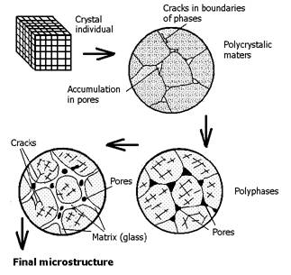
Figure 4 Shows the technogenesis of original raw material composed from minerals in finished product. The higher number of different minerals in raw material means complex resulted product formation (for example, microstructures of oxide ceramics-engineering ceramics).
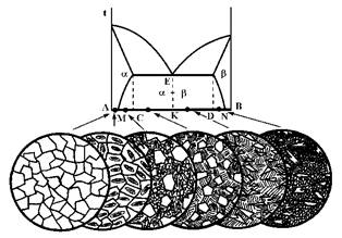
Figure 5 Melting scheme of two partially mixed melts and microstructures of resulting alloys by Szymańsky (1997).Simplified scheme of continuous microstructure transformation in example of two partially mixed components (they are transformed in raw material sintering process, as seen, for example, in optical microscope). Legend: Points between A-M and N-B have mostly single-phase composition and correspond to composition b in a and a in b being perfectly mixed (slightly different from pure components). Microstructure in points between M and C (or D and N); the first individuals of less present component are separated (b in a components and visa verse). More separated components (b in a, b+a, a in b) are formed in C-K and K-D area.
Microstructure
formations of metallurgical alloys are considered as a quite simple (see Figure
5). The more complex microstructures are formed in multi-component
technolithes.
Chemical
compositions of technolithes are expressed using main oxides. This concept is
shown in Table 1 where you can see common fireproof technolithe overview
including mineral compositions of original mixtures, main oxides, and thermal
intervals of their wear-away.
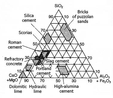
Figure 6 Technolithe positions in SiO2-(MgO+CaO)-(Fe2O3+Al2O3) system.
Triangle
diagrams can be used for representation of main oxides in individual
technolithes as well. SiO2-(MgO+CaO)-(Fe2O3+Al2O3)
diagram in Figure 6 shows visual example of common cement technolithe areas.
Sophisticated
photo-documentation is integral part of technolithe studies.
In the
group of technolithes1, it is possible to differ the same mineral
classess and subclassess as in the case of natural rocks. Therefore composition
of technolithes always depends on composition of initial material mixtures and
technological processes, mineral associations of technical materials are put
along according to individual technolithic groups.
A survey of
common heatproof technolithes, mineral and rock composition of necessary
materials, the mineral composition of the final product, the chemical
composition and the temperature stability of technolithes are synoptically
summarized in Table 5.
Table 5 Survey of common heatproof matters, their
composition and temperature of application.
Species of the heatproof matters |
Original materias |
Mineral components of the product |
Chemical contant of the main materials |
Application |
silica |
Quartz rocks, cherts + up to 5% of CaO |
cristobalit, tridymit, wollastonite |
over 90% of SiO2 under 5% of CaO |
up to 1710oC |
Silica glass |
Vein quartz |
amorphous SiO2 |
over 99% of SiO2 |
up to 1710oC |
Silica chamotte |
kaolin, clay stone, clay, quartz send |
mullite, cristobalite tridymite, quartz |
10-30% of Al2O3 |
up tp 1670oC |
Clay (normal) chamotte |
Heatproof clays, claystones |
mullite |
35-45% of Al2O3 |
up to 1750oC |
High clayey chamotte |
Heatproof clays, claystones, hydroxides and Al-oxides, Al2SiO5-minerals |
mullite, cristobalite, corundum |
45-60% of Al2O3 60-75% of Al2O3 over 75 % of Al2O3 |
up to 1840oC do 1900oC do 1950oC |
Not molton (molton) mullite |
Al-hydroxides and oxides, sillimanite, andalusite, kyanite |
mullite, cristobalite, corundum |
60-85% of Al2O3 |
up to 1960oC |
Not molton (molton) corundum |
Al-hydroxides and oxides |
corundum, mullite |
over 85% of Al2O3 |
up to 1960oC |
Common spinel magnesite (chrommagnesite) |
sintered magnesite magnesite -chromite + Fe2O3, SiO2, Cr2O3 |
periclase periclase, spinel |
over 80% of MgO 30-70% of MgO 10-30% of Cr2O3 |
up to 1700oC |
Dolomite with fixed CaO |
dolomite |
calcium silicates, periclase, CaO |
about 40% of CaO |
up to 1900oC |
Dolomite with free CaO (cements) |
dolomite, limestone, diatomite, magnesite, hematite, heatproof clay |
periclase, wollastonite, cristobalite, di-tri-calcium silicates |
about 35% of MgO 15-25% of admixture |
up to 1780oC up to 1900-2000oC |
Chromite |
chromite |
chromite |
over 80% of Cr2O3 |
up to 2000oC |
Carborundum (Si-carbide) normal |
carborundum |
carbide of silicon |
up to 80% of C |
up to 2200oC |
Carborundum high valuable (recrystallized) |
heatproof clay organic cement |
Mullite, cristobalite |
over 80% of C |
up to 1700oC |
Carbonaceous ceramic |
grafit, heatproof clays |
carbon, mullite, cristobalite |
30-80% of C |
up to 1700-1900oC |
Carbonaceous recrystallized |
graphite |
carbon |
80-100% of C |
up to 2500oC in a reducing environment |
Carbonaceous coccoid |
coccus |
carbon (microscopic) |
over 90% of C |
up to 2500oC in the atmosphere |
The mineral
composition of gannister is in fact given by types of initial materials, their
mechanic processing, a sort and amount of admixtures and a way of firing.
Figure 7 Modification transitions of SiO2 in
the row quartz - tridymite - cristobalite - glass in dependance on a
temperature (Fenner 1913).
Prevailing minerals are polymorphous forms of
SiO2: quartz, cristobalite and tridymite (see Fig. 7). Their optical
properties are summarized in the encyclopedy of menerals. Therefore we aim at
the microstructure of gannister and identification of individual phases here.
In thin sections of gannister, at a low magnification, one can observe coarse
fragments and fine-grained matrix, which are connected by gradual interfaces
(reflecting the granulometry of the used material). In a common fired
gannister, the coarse fragments illustratively document a type of used
quartzite. The microscopic characteristics of quartzite stay in fact not
changed, although the mineral composition changes. Unchanged relict
quartz (of primary genesis) occurs in a
fired sample. The quartz transition proceeds from the surfaces of grains along
the syatem of irregular cracks. The cracks form at a reversible transition of
α-quartz to β-modification at 573°C (see Fig. 7). This phenomena is
well perceptible due to the fact that the transition first manifests at clasts
with a large of specific suface. Very well perceptible transition only comes
through at the temperature higher than 1250°C. Microscopically „amorphous“
cristobalite is a product of the transtition of quartz grains. It is so
fine-grained that it causes opacification of those parts of quartz grains,
which have already been transformed to cristobalite. The share of the
transformed quartz in coarse fragments is usually significantly higher in
quartzites with larger quartz crystals, in which cristobalite only forms thin
linnings and fillings of thin crack and the original mosaic microstructure is
preserved. On the contrary, in quartzites
with much lower share of quartz, wider cristobalite rims form with
decreasing size of grains. The transition to cristobalite in the cement is
practically finished, so only isolated coarser quartz grains „shine“ among the
coarse fragments (at observation in CPL). The fineness of cristobalite
documents its formation directly from
quartz, without a presence of melt. Tridymite is coarser-grained and forms by
crystallization at the presence of the glass melt in matrix, i.e.
fine-grained gannister matter, sealing the coarse-grained fragments of
the original quartzite. Typical tridymite forms in gannister are compound
triplet crystals, which appear lanceolate twin-like in longitudinal sections. A
prismatic form is less frquent. It is more common in a recrystallized matter of
used gannister, namely in the zone corresponding to the tridymite
stability zone, i.e. up to 1470°C. Results from optical characteristics, in
comparison to quartz, tridymite has somewhat lower birefringence. In a context
with a smaller size of crystals and hence smaller thickness of their
sections, its birefringence comes through as lower intereference colours -
first rank gray. The lanceolate crystals of tridymite form a basic frame
of the gannister matrix. The high temperature SiO2 modifications
contant is variable in gannister. It usually fluctuates between 0 - 37 % of
quartz, 14 - 53 % of cristobalite, 14 - 71 % of tridymite. The contant of glass
melt and accessory minerals is about 9-20 %.
The share
of accessory minerals and glass melt depends on the composition the
initial quartzites. These minerals usually concentrate in fine-grained parts of
gannister and along with fine quartz and admixtures, they form matrix.
Accessory minerals, the amount of admixtures and cooling speed of the glass
melt also play a role at formation of other authigenic minerals. A
product of a reaction of SiO2
+ CaO - pseudowollastonite (Ca3Si3O9) is amost
always present. Due to the presence of other oxides (particularly Al2O3,
FeO, Fe2O3, MnO, TiO2 and oxides of alkali
metals), other phases occur. E.g. monoclinic pyroxenes, frequently solid
solutions of gannister, hedenbergite and johannsenite form. They are pleochroic
in yellow-green up tp green shades (the intensity of pleochroism depends on the
hedenbergite component content) or in shades of brown up to reddish pleochroic
augite. At the particularly high Fe (12,5 % of Fe2O3)
content, an opaque magnetite and a deep purple showing through hematite
contants increase in matrix. Of other minerals, deep red monocalciumferrite
(CaO.Fe2O3) and yellow-bown dicalciumferrite (2CaO.Fe2O3)
may occur. The minerals have high birefringence, most of them aree
conspiciously coloured and some of them are pleochroic. Thus, in matrix, at the
observation in CPL, they are noticable as high birefringent particles despite
their little sizes. But it is impossible to determinate the other optical
constants of them. Along with yellowish or braunish coloured glass matter, they
are carriers of gannister light yellowish up to ochroid brunish colouring.
At the microscopic
evaluation of gannister products, firs of all, contain, microstructure and
distribution of tridymite and percental abundance and size of a untransformed
quartz shoud be considered. The quantitative ratio of both the
minerals is possible to identify planimetricly.
Microscopic
characteristics of used gannister are somewhat different and they reflect
conditions in places of its application. A prevalent part of gannister is used
for linings of metallurgical furnaces, coking batteries and for vaults of glass
furnaces. In all above listed cases, the point is an one-sided affect of a high
temperature, slag, dust and volatile components. All of these factors come come
through as changes of microstructure and a mineral composition. A formation of
zones, macroscopically distinguishing from each other, is characteristic. E.g.
at chamotte blocks of the Siemens-martin furnace one can observe 4 basical
zones: primary, transient, black and gray. The differences in the chemical and
mineral composition of individual zones
are listed in Table 6.
Table 6 Table demonstrating changes in the chemical and
mineral composition of four basical zones of chamotte used in the
Siemens-martin furnace.
|
|
Primary
zone |
Transient
zone |
Black
zone |
Gray zone |
|
SiO2 |
94.79 |
85.90 |
86.28 |
92.06 |
|
TiO2 |
1.00 |
1.80 |
0.60 |
0.18 |
|
Al2O3 |
0.13 |
1.52 |
- |
0.05 |
|
Fe2O3 |
0.64 |
3.25 |
5.39 |
3.10 |
|
FeO |
0.28 |
0.43 |
1.63 |
1.14 |
|
MnO |
0.01 |
0.04 |
0.69 |
0.33 |
|
MgO |
0.30 |
0.31 |
0.76 |
0.46 |
|
CaO |
2.47 |
6.62 |
3.73 |
2.05 |
|
Na2O |
0.09 |
- |
0.06 |
0.13 |
|
K2O |
0.13 |
0.29 |
0.42 |
0.22 |
|
annealing
loss |
0.25 |
0.06 |
0.23 |
0.83 |
|
pseudomorphs
after quartz, metacristobalite |
26 |
26 |
11 |
- |
|
tridymite |
54 |
62 |
75 |
- |
|
cristobalite |
- |
- |
- |
69 |
|
devitrificated
glass, pseudowollastonite |
20 |
12 |
- |
- |
|
brown
glass, orthosilicate and magnetite |
- |
- |
14 |
31 |
The primary
zone ordinarily stays preserved up to the of 1100°C. It is light ochroid, with
an uneven grainy fracture, perceptible pores and visible white
grains of the original gannister. The thickness of this zone depends on the
total thickness of the block, i.e. it corresponds to the certain degree of
deterioration and gradually gets thiner. This zone gradually passes into the transient
zone. Its thickness reaches
approx. 6 cm and corresponds to a temperature of 1100-1350°C. It is
macroscopically darker than the primary zone, there are distinct white grains
in its fracture - coarser quartzite fragments. In a microscope, it is
evident that in comparison to the primary zone, number of them decreases and
the share of matrix increases. The quartz grains are strongly cracked and
transformed to isotropic metacristobalite. They are lined with crystallic
matrix with a confining microstructure, formed by approximately 25.10-6m
sized acicular and lanceolate tridymite crystals. The contant of a glass phase
and yellow-brown, short prismatic pyroxenes also increases. Besides them,
wollastonite and magnetite also occur. Towards the center of the furnace, the
transient zone passess into the tridymite zone (so-called black zone).
Its thickness is about 5 cm and assumed temperature of crystallization 1450 -
1540°C. The name itself says that it is
macroscopically fresh layer, in which one can still observe isolated white
quartzite grains. However, the fragments of quartz already do not occur in this
zone. Tridymite prevails here. It forms either feltlike cross section after coarse
quartz fragments and it participates at the composition of matrix at the same
time. It reaches up to 500.10-6m (i.e. in comparison with tridymite
in the transient zone, its size increases approx. forty times). It is almost
parallelly distibuted in the direction of a temperature drop. Further,
cristobalite occurs in this zone. Cristobalite has smooth lepidoblastic
microstructure and it is isotropic. In matrix, the matter surronding coarse
tridymite is yellow up to brownish and contains opaque magnetite, further
monticellite and fayalite (formating as
products of the decomposition of pyroxenes, unstable at high
temperatures). The last zone - the cristobalite one is gray, in comparison to the previous one
very thin (about 3 mm) and forms at a temperature of approx. 1540°C. It is
even-grained, tridymite does not occur here. Original fragments of quartzites
distinguish just in their finer microstructure. Cristobalite is lepidoblastic,
often cumulated to rounded aggregates of 0.1 - 0.3 mm size, with a mosaic-like
microstructure. Individuals of cristobalite reach up to 20.10-6m.
One can observe intergrowths (symplectites), polysyntetic twins and
pseudomorphs after tridymite. The intercrystal spaces are filled with a braunish
glass melt, fayalite and magnetite microlithes. In the case of a high local
warming-through of overloaded vaults of furnaces, the tridymite zone may be
considerably reduced or absent. On the contrary, the cristobalite zone is
totally absent in gannister from the bar screens of checker chamber of the
Siemens-Martin furnaces. In average, temperature does not exceed 1300°C here.
Except of automorphic crystals of tridymite, there was also pseudowollastonite
identified in the black zone. Its contant decreases from the contact to the
surface. The surface is formed by a microscopically pellucid glass layer
with isolated crystals of magnetite, possibly of hematite. This glass melt
dissolves and corrodes tridymite and contains prismatic pyroxene of the
hedenbergete type in a contact with the tridymite zone. Gannister from coking
batteries has also a similar distribution. The cristobalite zone is absent. The
tridymite contains a considerable amount of carboneum matters and graphite.
Pseudowollastonite concentrates in the transient zone.
Zones of in
fact similar composition and extent as in the case of gannister from the
Siemens-martin furnace form in gannister in the vaults the glass furnaces.
However, they have significantly lower Fe-components content. Only anisotropic
lepidoblastic cristobalite occurs in the cristobalite zone. In a finer form, up
to 50.10-6m, it occurs in places of originally coarser fragments of
quartzite. Coarser-grained cristobalite, up to 150.10-6m, is a
product of a tridymite transition in matrix. Rarely, one can identify
pseudomorphs after tridymite. This cristobalite is sealed with a yellowish up
to yellow-brownish glass melt, which contains about 20. 10-6m sized
dendrites of secondary cristobalite. According to the development of crystals,
which is typical for cristobalite formed during the glass devitrification, it
is apparently melt crystallization. About 7 -8
cm from the contact with a batch, the tridymite zone without free
quartz, with coarser-grained tridymite in matrix and with an isotropic
cristobalite in places of original coarser grains of quartzite. Further, high
birefringent silicates are present in matrix.
An
application of microscopic methods represents an essential part of a
technochemical control of products in a glasswork. Streaks, cells, products of devitrification
and occlusion are microscopically watched. A glass type can be determined by a
identifyind of refraction. A temper, its character and distribution can be
evaluated by a birefringence measurement. A microscopic study is applicated at
a material control, at a dust counting and at a study of a corrosion of heatproof materials caused by
a glass melt.
6.1 Mineral phases
From the
listed mineral phases, there is α-cristobalite (SiO2) present
in the technolithes. The mineral has a tetragonal symmetry and is stable at low
temperatures. During heating to 198°C - 240°C, it transforms to a cubic β-cristobalite
(metacristobalite) that is also stable at high temperatures. It forms
from quartz at the temperature ranging 1000°C - 1470°C or from tridymite over
1470°C. Cristobalite formed directly from quartz is so fine-grained that it
seams to be appearently amorphous - isotropic. It forms a lining around the
quartz grains or it occurs in cracks fillings. If the fillings are formed by
cristobalite, they are ordinarily poorely transparent, translucent and darker.
If it is heated to a higher temperature than 1600°C (e.g. in a gannister
gray zone in a vault of the
Siemens-Martin furnace or at lower temperatures in a work-zone of
gannister in a vault of a tank furnace. On the contrary, in a crystallization
process in glass, its typical shapes are dendritic aggregates of prismatic
crystals, joining at a 900 angle
to a central, axial crystal. A pyramidal up to clubbed ending of the
individual needles is typical for cristobalite and frequently occurs.
The
high-temperature cubic modification cristobalite has n = 1.486. An assemblage
with quartz occurs in glass. It is flaked formed, in gannister and dendrites
with rectangular, clubbed ended arms.
Another SiO2
form is tridymite. Rhombic a-tridymite transforms to hexagonal
β-tridymite at 117°C and to
γ-tridymite at 163°C. It forms from quartz at a presence of melt
between 1200 - 1470°C. Over 1470°C it transforms to cristobalite.
Unlike
cristobalite, tridymite is usually coarser-grained and forms twinned intergrowths
on (110). In a lengthwise sections, they are lanceolate or wrim-shaped. In a
cross section, they occur as twins, easily recognizable in XPL according to a
different extinguishning of the both individuals.
The cross section can also be hexagonal. It sometimes crystallizes in a form of
prismatic crystals. Described shapes are common in gannister, where they form
matrix along with glass. If it
crystallizes from glass, it forms stellar spherulites with 600 angle
of main arms forming diagonals of the hexagons. Lateral, long prismatic
crystals are connected to the diagonals. Sometimes, they form hexagonal plates
too. The plates are very thin in a cross section.
Mullite Al2[O|SiO4]
occurs in chamotte, or in the contact ot chamotte and glass. It has a rhombic
symmetry and forms long prismatic up to acicular crystals with almost square
cross sections. A longitudinal cleavage on (010) is often perceptible. In
chamotte or high clayey material, occlusions are often accompanied by
corundum an nephelinite.
Corundum
Al2O3
has a trigonal symmetry. It is often accompanied by mullite and nephelinite in
occlusions. It forms xenomorphic grains, sometimes is columnar. Cross sections
are triangular- or hexangular-shaped. It is not cleavable, it has just a cross
division on {0001}. It is ordinarily pellucid.
Baddeleyite
ZrO2 crystallizes
in a monoclinic symmetry, forms plate-like or short prismatic pyramidally ended
crystals. It may occur in a shape of rounded elongated grains, often is
ovoid-like shaped. It has a perfect cleavage on {001}. In thin sections, it is
colourless up to brown, rarely pleochroic between brown and yellow or green. A
typically high refringence and birefringence, overlapped with a colour of the
mineral itself, distinguishes it from other minerals.
Kaliofilite
KAlSiO4 has
a hexagonal symerty. In cross sections, it forms short prismatic crystals,
imperfectly cleavable on {10ī1} and perfectly cleavable on {0001}. It
contains up to 20 % of nepheline in a solid solution. Its hardness ranges 5.5 -
6 (cloce to orthoclase). It is colourless in thin sections, its specific
gravity ranges 2.49 - 2.67. Values of refractions oscillate between: a = 1.527 -
1.533, g = 1.532 - 1.537, D = 0.005, Chm (-). The variability is
connected with an existence of solid solutions. It is very often optically
identified as nepheline. It has a negative relief and a low birefringence in
cross sections.
Carneigieite
Na2O.Al2O3.2 SiO2 represents a high-temperature
polymorphous phase of nephelinite.
If it is
cubic with a refraction n = 1,51, it forms from nephelinite at temperatures
higher than 1248°C. In cooling below 687°C, its symmetry changes to a triclinic
one. It forms xenomorphous grains, rod-like crystals and also needles. During
very slow cooling, it transforms to
nepheline.
Its
polysyntetic twin lamellae are similar to albite that has higher
refractions. It is hard to differ from
nepheline according to a lower refraction and a polysyntetic lamelling.
Often
occuring outstanding features of the formation of occlusions by devitrification
are geometrically symetric shapes. Some of the shapes are so typical for a
morphology of the mineral that they enable to determination without detecting
of the other optical parameters. However, on the other hand, every mineral
species occurs in a series of morphological varieties and various
microstructural configurations. They can occur as unoriented isolated crystals.
Or as perfectly developed spherolites. The differences are connected with
different physical conditions of crystallization. Therefore in some measure
they enable to idetify passed processes. Reasons of the devitrification can be:
lack of uniformity of the glass melt comming through, e.g. in the surroundings
of occlusions and streaks, change of composition of glass or too low
temperature in a certain part of the furnace or combination of several factors.
In a processing of a „perfectly“ homogenous glass melt, viskozity decreases
with rapid cooling. It is so significant that microlites of the phases are
prevented from crystallization, even in spite of growing of the speed of
crystallization to a certain maximum.

Figure 8 The chart illustrates crystallization ability of a hypothermic melt, which is given as a function of the undercooling, characterized by a behaviour of viscosity. Legend: VZK - the formation of crystallization nucleuses in the unit volume in the unit of time, at the given degree of undercooling; LKR - linear ability of crystallization.
A
crystallization ability is in fact given by a spontaneous
formation of crystallization nucleuses in a volume unit during a time unit at a
given degree of undercooling.
The growing
viscosity „slows down“ diffusion of ions, which is necessary for the growth of
the released nucleuses and for releasing of other ones. From the Fig. 6, it is
further obvious that maximum of LKR is flatter than maximum of VZK, does
not correspond to it and is usually
removed towards a higher temperature level.
At a low viscosity, there are better condition for a faster growth of a
lower number of crystallization nucleuses than for a higher number of them (in
a zone of VZK maximum values) at a little higher viscosity already. A
different LKR and VKZ maximum values are further a cause of
various microstructures and various development of crystals that form at
different temperatures. At the beginning of the crystallization - close below
liquide temperature - at a low degree of VKZ and LKR, isolated minute crystals
are released. They are rather hypauthomorphic and they are in equilibrium with
the melt. Automorphic crystals of a maximum size develope with a rising
temperature. Number of them rises very quickly and their size somewhat
decreases at the same time. A columnar crystal habit is more frequent. The
formation of spherulites proceeds over boths maximum values (LKR, VKZ). Number
and size of spherulites falls with a crystallization temperature drop. Tiny
stellar spherulites appear and hypautomorphic skeleton-like crystals are
formed. In the end, after the devitrification, hypautomorphic
skeleton-like crystals form. In the devitrification, formation of more mineral
species proceeds, particularly if the composition the glass melt is close to an
interface crystallization fields. Mineral assemblages form this way.
A range of
composition of common lime glass lies in an area, where devitride or wollastonite,
exceptionally cristobalite, crystallizes as a primary phase. A SiO2
cristallization in cristobalite, possibly tridymite form proceeds after CaO
depletion of the glass. CaO is bound in above listed silicates. In
glasses with the MgO content over approx. 3 %, diopside ordinarily forms
instead of wollastonite and plagioclase forms instead of wollastonite in
clay-rich glasses.
Devitride
Na2Ca3.[Si3O8]2 forms by crystallization in
Na-rich glassess. It occurs the most frequently in a flat glass and in some species
of container flints. It crystallizes at approx. 725°C. It is stable up to 1045°C, wollastonite - Ca3[Si3O9]
dissociates into a melt over this temperature. It frequently occurs on bottoms
of flat glass melting tanks. Its crysral symmetry is rhombic, it ussualy forms
acicular crystalls, mutually felt-like intergrowing. Fanlike aggregates and
besom-like, penicillate and bunch-like reaching up to a few millimetres. These
forms can be considered typical. The shape and microstructure manifests a fast
crystallization from a very viscose melt. In thin sections, it is colourless, pellucid, with an indistinct
cleavage, α =1.564, β = 1.570, γ
=1.579, D = 0.015, Chm (+), Chz (+). Wollastonite
is a similar mineral. Devitride can be distinguished from wollastonite
according to brush- or fan-shaped bunches of needles, possibly, in the case of
idividual crystals, on a basis of its lower refractions.
b-wollastonite Ca3[Si3O9]
(parawollastonite)
the most frequently crystallizes in a container flint that is somewhat CaO-richer
than the flat glass. It can be found by a bottom in corners of the melting tank, e.g. due to an exsolution
of heavier limy component of stone. It is stable up to 1180°C and transforms to
pseudowollastonite over this temperature.
It has a
monoclinic symmetry and white colour. The crystals are acicular, if perfectly
developed, elongated with lath-like up to wide lath-like cross sections. Laths,
which are not flat terminated, are typical for
wollastonite. The temination of the laths is usually typical. In thin
sections, a parallel „fringing“ comes through, as if the termination of the
crystal would consist of several parallel individuals of a various lenght.
Among them, one can find nonuniformities, which are parallel to
the elongation and getting into the crystals. In fact, the nonuniformities are
clevage cracks on {100}. b-wollastonite is perfectly cleavable on {100} and good clevable on
{001} and {102}. It forms radial and fan-like aggregates. Rounded rims of the
crystals manifest their reverse dissolution. It can be accompanied by devitrite
or cristobalite, which crystallized directly on the large laths of
wollastonite.
It has a
positive relief (α =1.616 - 1.621, β = 1.623 - 1.633, γ =1.631 - 1.635), D = 0.014 - 0.015, Chm
(-) , Chz (+,-).
It differs
from devitrite in shape, (if it is prismatic), in a character of zone and a
higher refraction. From anorthite in an absence of twinned laths, from
pseudowollastonite in a charaktere of zone. It is the most often confused with
devitrite.
α -
wollastonite (pseudowollastonite) CaO.SiO2 occurs less frquently, sometimes
along with with b-wollastonite, into which it transforms below 1180°C. Alike b-wollastonite,
it occurs in a container flint, where it can form at slow cooling and
the high CaO content. From the β-modification it differs in a triclinic
symmetry, it crystallizes rather in a shape of short prisms and hexagonal
plates. Larger (n.10-6 m) hexagonal forms of b-wollastonite
are pellucid in a central part and they become tarnished towards the rims.
Sometimes, they consist of dendriform aggregates, similar to cristobalite.
However, they differ from cristobalite in their significantly higher
refractions and birefringence.
a-wollastonite has α =1.607 - 1.618, β = γ =1.649
- 1.663, D = 0.044, Chm (+) , Chz (-) .
a-wollastonite differs from b-wollastonite in its significantly
higher birefringence, a character of zone and a shape of cross sections.
Diopside
CaMg[Si2O6]
Diopside is
a less frequent product of devitrification than wollastonite. It is ordinarily
found in a coloured container flint with the MgO content over approx. 3 %.
It forms
isolated elongated prisms or it forms sherolites .
If they come out along streaks, they are considered to be an evidence of the
nonuniformity of the glass.
It has a
monoclinic symmetry, its optical and physical properties are summarized in the
encyclopedy of minerals. Unlike wollastonite it has an inclined extinction,
somewhat higher refreactions and birefringence and always positive length
character. It is distinguishable from devitrite by its incclined
extinction, positive relief and somewhat higher birefringence.
Jeffersonite
Ca (Mn, Zn, Fe, Mg) [Si2O6]
The mineral
is a Zn-variety of schefferite (diopside + hedenbergite with Mn and Ca). Thus,
it is certainly analogical to diopside,
where magnesium is isomorfously replaced by manganese, zinc and iron. It
crystallizes from special glasses, particularly zincmagnesium ones.
From
optical parameters, it is possible to state: α = 1.682, β = 1.690,
γ = 1.710, D = 0.028, Chm (+). It has an inclined extinction,
at the angle of 360 towards the elongation.
Cristobalite
is usually the most
common modification of SiO2 crystallizing at the devitrification
process, even if it crystallizes outside the zone of stability, i.e. below 1470°C. At a longer heating below this
temperature, cristobalite transforms to a low-temperature modification of SiO2
- tridymite. It goes through a
series of stages. The original rectangular dendritic forms, terminated with
pointed columnar crystals which corresponds to a cubic system of
high-temperature cristobalite transform into hexagonal stellar aggregates with
lateral arms connected at an angle of 60°. These stars can sometimes
remind aggregates of nepheline. In a series of transient stages, the final form
is hexagonal lamellar tridymite. Sometimes, the both forms of the crystal occur
together. The stellar aggregate of the transient form is edged with very fine
dendritic cristobalite. Due to a contraction of volume at cooling induced by a
reversible transformation of β-cristobalite into α-modification, a
net of cracks forms in a place, where devitrification proceeded. A relateve
rare form of cristobalite, crystallizing in boronsilicate glasses, misses a
typical rectangular structure and consists of irregularl fragments. Its
physical and optical parameters are listed in the encyclopedy of minerals,
other facts in a passage regarding occlusions of heatproof materials.
The occurrence
of tridymite indicates that the crystallization of SiO2 proceeded in
a longer time interval. Cracks surrounding tridymite may also form.
Plagioclases
are in detail
described in a chapter about groups of minerals and in the encyclopedy of
minerals. They crystallize in high-aluminous glasses.
Bariumdisilicate
BaO. 2SiO2 has a rhombic symmetry. It crystallizes from barium glassess, where it
represents a typical product of devitrification. In thin sections , it forms
long prismatic elongated crystals, with lamellar or pseudohexagonal
cross-sections (sometimes with a central cavity) or less developed crystals in
a shape of iregular flakes. Refractions range α = 1.595 - 1.602, β =
1.610 - 1.617, γ = 1.613 - 1.632, D = 0.024, Chm (-) ,Chz (+)
. It is distinctly cleavaable on {001},
{010}and {100}.
Willemite
Zn2[SiO4] may crystallize from glasses with the relatively low ZnO content. It forms small hexagonal prisms. Its
optical and physical properties are listed in the encyclopedy of minerals.
Alamosite
Pb[SiO3]
has a monoclinic symmetry, it occurs in devitrification products of heavy lead
glasses. In soft lead glassess, cristobalite occurs. It forms pellucid or
white, fibrous up to long columnar crystals, which are often spherulitic. It has a specific gravity 6.49, hardness 4.5
and a diamond lustre. It is perfectly cleavable on {010}. α = 1.947,
β = 1.961, γ = 1.968, D = 0.021, Chm (-), Chz
(-).In nature, it occurs in a zone of oxidation of lead deposits.
Nepheline
is in detail
characterized in the encyclopedy of minerals. It was detected among the
occlusions of the heatproof materials. In glass, it ordinarily forms aggregates
on the interface of natrium glass and chamotte and high-aluminous heatproof
material. It is usually accompanied by mullite, possibly corundum. It differs
from mullite in shape, lower refractions and a negative length
character.
Mullite is also listed in the encyclopedy of
minerals and it is discussed in the passages above. It forms in the interface
of glass and chamotte or in special glasses with the Al2O3 content
of over 40%.
In opal
and opalescent glasses, devitrification is induced on purpose. However, the size
of crystals is usually smaller than a resolving of a polarization
microscopeand. An electron microscopy is successfully used for the study of them.
The
microscopic determination of devitrification products serves not just
for the identification of operating faults, but also for a study of
equilibrium states of the glass using a method of crystallization in gradient
ovens. It is possible to assess the liquide temperature, if a
volatilization of some of the components does not come up and to find out a
value of the crystallization pressure. At these mesurements, incised zones in a
form of “overflowed drops” with a
different refraction sometimes occur on the surface of the glass before
a precipitation the first crystallic phase. It is probably a detached liquid
phase which dissapears during a following heating. The first precipetation of
the crystals proceeds in these spots.
A binocular
microscope is used for watching of surface defects, cracks and streaks.
Deposits on the internal sides of a container glass can be removed with a putty
knife and watched in an immersion liquid. Sodium sulphate can form on a surface
of glass to which alkali (e.g. Na2SO4) were
partly brought or in which a reaction of fumes of SO2 and alkali in an oxygenic
atmosphere proceeded. It usually occurs in a melt, which temperature does not
exceed approx. 1200°C. Na2SO4
decomposes at a higher temperature. Sulphate incrustations form either by a
condensation or by a straight reaction of SO3 and alkali on the
surface of the glass melt.
Na2SO4 has a rhombic symmetry. It forms amorphous film
of a bluish shade. Due to a movement of the glass melt during its formation,
the film is usually not continuous and is separated into small isles. The film
is partially miscible with the glass melt. Its shape is often eliptic up to
teary. It is only perceptible in a form of acicular crystals after a recrystallization
on the surface. α = 1.471, β = 1.477, γ = 1.484, D = 0.013, Chm (+),
it has a prallel extinction. Theformation of the sulphate may be caused by a
crystallization of tridymite in the surface zone of glass. On the contrary in
an reducing environment, in a glass enriched with alkali, its decomposition,
leads to a crystallization of silicates. Due to the air humidity, leaching of
alkali proceeds on the surface of the glass. If the alkali are not removed,
alkali carbonates, particularly Na2CO3, filamentary
crystals form on the surface. These are easily microscopically
identifiable as birefringent dendritic formations. The glass surface is
corroded, covered with dendritic „etchings“ after a removal of the carbonates.
For its distinguishing from similar cristobalite we use an immersion liquid
with the same refraction as the refraction of glass. In the case of dendrites,
the surface relics disappear. In the case of the presence of cristobalite, the
relief is conspicious.
For a study
of plied and flashed glass, material cross sections have been successfully
used. The cross sections enable watching of e.g. a temper between both of the
layers.
The streaks
usually represent locations of glass of different composition with a different
specific gravity and a different comming through relief. At a microscopic
study, Becke lines edging the streaks are typical. Glass streaks appear due to
a series of faults, e.g. an insufficiently homogenized glass batch, a too
coarse-grained material, a melting of a heatproof material of port arch and
jamb wall, bringing devitrification products back to places with a higher
temperature by a flow and changes of a composition of the melt.
The streaks
with a lower refraction than surrounding glass have usually a connection with
SiO2. Its source can be a sand of the glass batch or a corrosion of
a gannister flying arch. The streaks with higher refraction form either due to
a partial assimilation of a fireclay or an aluminous heatproof material or due
to a contamination with wollastonite. The following Table 7 gives an
outline of character of the contaminants.
A suitable
immersion liquid (i.e. with a close refraction) placed into a microcell should
be used to study the streaks of fragments of an uneven glass. The glass should
be immersed into the liquid. The
microcell should be made of a tiny vial cross section. A ring of a
thickness of approx. 5 mm should be cut off cut from the cross sectio. Finally, the ring should be
sealed with an epoxide to a microscope slide.
Table 7 Relation of a change of refraction with a
character of a contaminant.
|
0,1 %
enriching |
Refraction
change |
|
SiO2 |
-0,0005-0,0010 |
|
CaO |
+ 0,0025 |
|
Na2O |
+ 0,0007 |
|
K2O |
+ 0,0006 |
|
Al2O3 |
+ 0,0001 |
However, an
affect of the change of the chemical composition on the refraction is not very
significant. Therefore, a phase contrast is successfully used for searching of
streaks that only a little differ from their surroundings. The streak that is
otherwise indistinct displays a noticable shade, different from the surrounding
glass. That’s why the refraction is determinable by the immersion method in the
phase contrast. It is possible to to measure the refraction even more exactly
in a polarization microscope.
The cells
often occurs close the devitrification products. The phenomena can be explained
by an affect of a decrease of solubility of gas in the glass melt. The reason of a formation of cell is
microscopically identifiable, particularly if the cell contains crystallic
inclusions. However, the microscopic
watching destroys functions of the cell as a lens. Therefore, the glass should
usually be a little grind close to the cell to create parallel faces (the
grinding should be done bilaterally, in the case of a curved sample). The cell
should be covered with an immersion liquid with the same refrafraction as the
glass and driven through with a needle. Due to an underpressure in the cell,
the liquid is usually sucked inside. The crystals should be determined in an
environment of a homogenous immersion liquid. Bubbles caused by an oxidation of
carbon contained in a form of cementite in pieces of iron can be filled with
compounds of iron. According to a degree of oxidation, they are yellow-brown or
green or can contain iron in a form of a metal or an oxide. In an instance of a
decomposed sulphate that is only partially miscible with the glass melt, the
cells can contain Na2SO4.
Sodium sulfate can ocuur either in a form of spherolites or in a form of fine
cracked filling.
The
occlusions and the products of devitrification can be studied both in thin
sections and, if we aim at an identification of phases and a microstructure, in
grain preparations that enable us identifying of e.g. refraction. To prepare
the grain preparation, glass with an occlusion should be bruised into coarse
fragments. The ones which are suitable for another bruising, e.g. fragments
containing crystals, should be selected in a binocular microscope. It is
usually recommended to remove an excessive glass in a flame. Two hard
glass canes should be seamed to the glass with the occlusion fragment. After a
warming, the glass surrounding the occlusions should be pulled out by a fibre.
One gets the occlusion, which is covered with a film of glass. The grain
preparation contains only a minimum amount of glass then. If the occlusions or
the devitrification products are perfectly transparent, the thin sections made
of glass with occlusions can be thicker (up to 0,1 - 0,3 mm). In thin-walled samples, one may replace the
thin section by a thin fragment immersed into an immersion liquid with a
refraction similar to the glass. Crystallic inhomogenity in the glass come from
three sources. It can be a not completely melted stone, corrosion of a
heatproof lining or it can possibly be of products of crystallization of glass. To identify them,
according to need, one can use a refraction, a character of zone and a
birefringence. A very small size of crystal usually makes a determination of an
optical character of a mineral impossible. In a
microscopic study, we are not bounded just by a composition of the
material of occlusions, but we also observe their microstructure. We observe a
shape and a fire polishing of rims of the occlusion, their size and development
and distribution of crystals. In an interface of the occlusion and the glas, we
aim at ationauthigenic formations - secondary crystallic phases and streaks and
at manifestations of strain. These characteristic features usually can help us
both at the identification of occlusions itself and at an explaining of
a genesis of the occlusions. The basic reasons of the formation of occlusions
from the glass batch are:
- lack of easily soluble components of
the glass batch;
- low temperature during the melting of
glass;
- affect of a coarse-grained or
polydispersive sand, dolomite and other substances;
- insufficient mixing of
material;
- short time of the glass melting;
- irregular starting of the glass batch.
Therefore, it
is obvious that the most common occlusions of the glass batch are quartz
grains, partly or completely transformed to a high-temperature modification SiO2.
Further, these are minerals accmpanying quartz in sand, particularly accesory
minerals (zircon and chromiumspinel). Due to its genesis, we sort here an
allochthonous material brought by the glass batch, without being its part, e.g.
iron too.
At the
beginning, quartz occlusions (quartz grains in sand) keep their round shape
with a smooth surface and thin irregular cracks. Number of the cracks increases
with a rising temperature. The surface gradually becomes uneven, the cracks are net-like. A form of
SiO2 changes at the same time. surface of the grains becomes covered
with a layer of cristobalite or tridymite. The layer becomes thicker and it
fills the propagating cracks. Unlike in the case of quartz, the cracks are very
fine. Their minute size is a reason of a seeming homogenous appearance of these
linings and fillings. A less stable modification - cristobalite usually forms
as the first one. Its formation is, apart from other things, suuported by
present mineralizers (alkali). At the same time, in a direct formation
from quartz, the formation of cristobalite requires a simpler recofiguration of
a lattice than in the case of tridymite. Inside an original grain of quartz, cristobalite can be without a
distinct crystal form or it forms a typical lepidoblastic
microstructure, occuring e.g. in a cristobalite zone of gannister. Only on a
periphery of grains, where it forms from an equilibrium melt, it forms
skeleton-like crystals with orthogonally joined lateral prisms. The
prisms are a typical form of
cristobalite occuring in devitrification. Along with a gradual melting of sand
the melt becomes enriched with SiO2 so much that the skeleton-like
cristobalite also forms in isolation, outside the grains. However, it only
forms close the grains. Later, the cristobalite filling the crack and rims can
be partially or completely transformed to tridymite. Tridymite usually occurs
in acicular or lamellar forms. In central parts of completely transformed
grains of quartz, lanceolate-twinned tridymite was found, while the rims of the
grains were made of skeleton-like cristobalite. The lanceolate-twinnned
tridymite form occurs in gannister again.
Another
sort of occlusions of the glass batch are clayey ones. Aggregations of clay
usually come from an insufficiently washed sand and they form difficult soluble
occlusions. They are almost „amorphous“, only translucent, with crystals of
mullite of a size of n.10-6m order of magnitude. The mullite
crystals are perceptible just in the highest magnification. Occlusions of so-called heavy minerals
(rutile, zircon, chromite) accompanying quartz in sand are quite rare and their
genesis is the same. Dolomitic and calcitic occlusions usually containing
periclase grains linned with diopside are also rare.
Genesis of
sulphate inclusions have been discussed in surface defects. Due to an
partial miscibility with glass melt, the inclusions of sulphates make
lenticular forms, sharp bounded with glass. Their microstructure is irregularly cracked or filled with
spherolites. A contamination with a
metal iron brought into the glass with batch, is
always perceptible in a magnifier. However, a lead deposition in surroundings
of an iron corpuscle is microcopically observable e.g. in lead glasses.
A heatproof
material represents another source of occlusions. The heatproof occlusions are
the most common ones. Their composition and microstructure depends on a series
of factors. Particularly on a sort of the heatproof material, a placement of
lining which they release from, on temperature and on an action time of the
surrounding glass melt.
Due to an
action of alkali oxides, a melting down of a port arch proceeds.
Drops, usually containing small gannistere fragments, form on a gannistere
surface. Quartz is neither present on the surface of gannister nor occurs in
the occlusions. The occlusions are formed predominantly by a
lanceolate-twinnned tridymite. A dendritic cristobalite, usually linning
tridimite, is sometimes present. One can differ the occlusions of port arch
from the occlusions of batch on the basis of an absence of quartz. In an
initial stage of reaction with the melt, mineral composition and microstructure
of the chamotte occlusions correspond to the original material. They ordinarily
form hardly transparent irregular grains, containing very fine crystallic n.10-6m
sized crystals of mullite. Due to an affect of the glass melt, a accumulating
crystallization proceeds and mullite forms. Mullite occurs as long prisms and
needles up to 50.10-6m long, surrounded with the glass melt. Mullite
crystallizes in all chamotte species. Therefore in acid chamotte, it is
impossiple to e.g. draw a conclusion from its presence that the original
heatproof material was highly aluminious. In the contact of occlusions, an
external rim of aggregates of granular nepheline (KNa3[AlSiO4]4)
forms by reaction with the alkalic melt.
Its formation is considered to be typical for the chamotte occlusions
that were in a contact with the glass melt for a longer period. The nepheline
optical properties are listed in the encyclopedy of minerals. Its refractions
depend on a Na + / K+ ionts rate. Nepheline forms solid
solutions. In the rims of the chamotte occlusions, nepheline occurs in a form
of short prisms with hexagonal sections or it forms dendritic aggregates. In
occlusions that were in a contact with the glass melt for a longer time, the
aggregates can totally replace mullite and
b-corundum. In potassium glasses, nepheline can be replaced with
kaliofilite K[AlSiO4]. A skeleton-like microstructure of both of the
feldspathoids can be a cause of their confusing with cristobalite. They are
differentiable on a basis of comparison of their refraction to the refraction
of glass. Nepheline has higher refraction than a surrounding calciumsilicate
glass. If chamotte reacts with melt at a tmeperature higher than 1245°C, a
high-temperature polymorphous phases of nepheline called carnegieite forms. The
mineral has a typical polysyntetic lamelling. The retransformation to nepheline
is slow and both of the minerals can occur together. In high aluminous
chamottes, a decomposition of mullite and a formation of authigenic forms
proceeds by a chemical reaction with alkali oxides. Above a surface of the
glass melt, mullite decomposes to corundum and a melt due to alkali metals. The
process runs even at lower temperatures than the glass melting one. Then,
corundum can be transported by the melt to the glass melt, where it stays
preserved for a long time due to its high melting temperature, chemical
resistance and relatively large size of individuals (up to 1 - 2 mm). Corundum
forms perfectly developed hexagonal automorfic thin plates with a
distinct relief. Its cross section is lath-like Chz (+). Under the surface of the
glass melt, the erosion of melting chamber proceeds and chamber occlusions
appear due to the affect of streaming. Chamotte grains, ordinarily containing
felt-like mullite aggregates in the central parts, are brought from the chamber
occlusions to the glass melt. Mullite is usually long prismatic, the crystals
have almost square cross sections. The crystal ends are round, fire-polished. Sometimes, at a formation
of a rim of β-corundum and a melt, exceptionally α-corundum can be
also present. A bordering of β-corundum is similar to
α-modificacation. Its relief is less distinct (refractions are lower). On
the contrary its birefrefringence is considerably higher. In CaO-rich glasses,
plagioclase represents a final product of the melting of chamotte in the glass
melt. The transition of the occlusions to the melt can be either a gradual with
a wide range of irregularly scattered products or, contrawise, completely
direct.
Due to a
relativly coarse-grained microstructure and the content of chemically stable
minerals, the electromelted occlusions dissolve very slowly in the melt.
Their initial composition stays unchanged for a long time. Their material
composition is different and it corresponds e.g. with flaking off, a
penetration of the glass melt into cracks and cavities and with a washing up of
resistant crystals from a less resistant glass matter. According to properties
of the original materil, they mostly contain mullite, β- and
α-corundum and baddeleyite. A resistance of the mentioned minerals to corrosion caused by
the glass matter also increases in the same direction. a-corundum and baddeleyite stay preserved in the glass melt
for the longest time. Unlike secondary (authigenic) corundum, which forms on
the boundary between the chamotte occlusions and glass, primary corundum is
mostly xenomorphic. The secondary corundum is corroded by the melt and
it contains inclusions of baddeleyite. A distinct rim - streak with a higher
refraction than surrounding glass forms around baddeleyite. It gets to the melt
from a surface protecting coat. In a study of the genesis of the occlusions, it
is useful, if necessary, to make a comparison with a microstructure and
a mineral composition of the heatproof layers on the surface.
7 Chamotte
Chamotte is
the most sigificantly used in metallurgy. Here,
chamotte is exposed to the affect of high temperatures and is
simultaneously corroded by slag, metal or fluids. The temperature gradient and
diffusion of allochthonous oxides lead to the formation of
distinct zones with a typical mineral and chemical composition. The authigenic
phases correspond to a type of corroding environment and also to the
composition of chamotte.
Both
microstructural components: coarse grains of an opening material and
fine-grained matrix already become apparent macroscopically. They are the most
conspicous in a fracture. The surface the fracture is suitable for an advance
evaluating of chamotte. In a product of a
high quality, where the opening material in perfectly connected with
matrix, the fracture comes through the most of grains, so the fracture surface
is rather even. On the contrary, in a product with a looser bedding of
the opening material, these grains stay untouched in the fractutre and
they fall out. One can observe their prints in matrix. At the microscopical
study of thin sections, one can observe differences among the components. The
opening material is ordinarily transparent, yellow-brown up to gray-brown.
The mineral composition of the opening
material is in fact the same as the mineral composition of grains of a fired
shale or a fired clay. It is formed by mullite and a glass melt.
However, mullite is submicroscopic. It is not possible to distinguish its
individual crystals from a lower refractive glass melt. It is only possible to
assesss a total refraction of the opening material, which is affected by the
mullite/glass melt ratio and increases with a degree of mullitization. In the
incident light, the mullitized opening material is more reflective than weakly
mullitized matrix. In CPL, these grains are just indiscernible light without a
characteristic extinction of the crystal individuals. One can also observe a
birefringence of aggregate. There is an exception only in those grains of
shale, which contain kaolinite bacilarites mullitized by firing in rough conditions. This pseudomorphs are
perceptible, when watching in CPL, because the crystals of mullite keep a
parallel direction on the direction of the flakes of kaolinite. Preferentially
arranged aggregates, extincting almost simultaneously, form this way. In
CPL, besides the orientated aggregates of mullite, one can distinguish irregular,
anisotropic grains of quartz. Quartz is pellucid, its untransformed grains are
cracked due to a reversible conversion of α-quartz to the
β-modification. Fine-grained quartz and possibly also small crystals of
accessory minerals, e.g. rutile or zircon are of the primary genesis and they
come from the material.
Around the
grains of the non-plasics, noticable cracks form. Matrix of chamotte is lighter
and more porous than grains of non-plastics. They are parallel to margins of
the grain due to the affect of strong shrinkage of the bond-clay. Mullite is
weak-perceptible in matrix, it reaches 3-5.10-6m. Rarely,
particularly in the margins of a thin section, one is also able to distinguish individual
crystals. Hypautomorphous shape of mullite is only perceptible after its
preparation using fluorhydric acid. Size and shape of the mullite
crystals is affected by temperature and time of firing, way of cooling
and viscosity of surrounding glass melt. Mullite arranged to felt like
aggregates reaches a maximum size up to 50. 10-6m. At firing over
1200°C refraction of the chamotte glass melt decreases as a result of melting
of fine quartz and oscillates between 1.52 - 1.54. In the case of a brown glass
melt containing iron, its refraction
reaches values up to1.60 - 1.62.
Acidic chamottes contain a largeger part of
quartz both in a coarser-grained and a finer fraction. Grains of the
coarser-grained fraction are considerably cracked. These grains are also
unaltered, but considering their excellent adhering to the bond clay a thin
glass layer around the quartz grain forms (the bond clay contains fine-grained
quartz and also additives, therefore a large volume of glass melt forms there).
Close to a quartz grain, the glass melt is pellucid. Due to chemical composition changes and drop of viscosity needles of mullite of 2-5.
10-6m length appear. The mullite needles cause tarnishing of glass
melt. Mullit is oriented in the
direction of the gradient of diffusion of aluminous ions and viscosity, i.e.
perpendicular to the margins of the quartz grain. This interlayer has a crutial
affect on a strength and density of the
body.
The high
valuable chamotte has a suitable granulomertic composition and non-plastcs
excellent mixed with a bond-clay, which is uniformly distributed. The iron
content is very low and only in tiny fragments, so it deleteriously affects
neither temperature resistance of products nor changes of volume. Pores are
uniformly distibuted.
In a common
quality chamotte, the considerable free quartz contant particularly
perceptible. Its fragments reach up to 0.5 mm. Non-plastics is rather well
mullitized, individual crystals reach a size of 10-15.10-6m, but
mullite is completely indistinct. Only locally, it is possible to distinguish
its individual hypautomorphic crystals. However their size does not exceed 5.10-6m.
Pores are larger than in the high-valuable product and they are not uniformly
distributed.
Due to the
affect of cooling, a considerable change of density does not come up in the
major part of the lining. In spite of this fact, even macroscopically
distinguishing zones form in chamotte. The primary zone is light ochroid and
corresponds to an unused chamotte. The transient zone is darker, better
mullitized and contains a fine-scattered corbon both in pores and in
intergranulars of the non-plastics. The internal zone is usually densified by
authigenic minerls.
Carbon
releases the most intensively at a temperature between 450 - 550°C. In the
final stage, the setting of carbon leads to a comlete corrosion of chamotte.
The affect of alkali from charge manifests as a formation of authigenic
minerals. A thin densified layer containing nepheline and kaliophyllite forms.
Towards the transient zone, leucite and feldspars occur instead of them.
Further, mullite and glass melt are present in the transien zone. Besides
alkali minerals containing oxides, other minerals (pseudowollastonite, melilite
and gehlenite) may be present in the surface zone. These minerals form as
products of reactions with a lime slag or a charge limestone. Besides the
formation of anorthite, the decomposition of mullite may lead to the formation of corundum. At the chamotte
corrosion of the lining of blast furnace, elongated polysynteticly twinned
anorthite crystals reaching up to 0.5 mm are often identified. In a
regenerated chamotte from the
Siemens-martin furnaces, 5 - 6 mm thick glass layer forms in the
surface. The glass layer which contains acicular mullite crystals or corundum
tables and alkali-calcium-ferric silicates.
Chamotte
from ladles contains
excellent developed mullite both in the non-plastics and in matrix. Its pores
are filled with a glass melt and mullite needles. The surface layer is hyaline, it usually
reaches a thickness of 0.5 - 2 mm. In the contact with the transient zone,
acicular mullite occurs. Towards the surface,
mullite is replaced with dendritic crystals of melilite, grains of
spinel (MgAl2O4), hercynite (Fe2+Al2O4),
galaxite (Mn2+0.9Mg0.1Al1.9Fe3+0.1O4
) or lath-like anortite (Ca[Al2Si2O8]).
In the
surface of cast material a thin coating 0.2 - 2 mm thick forms.
At the casting of a rimmed steel, only a hyaline layer forms in the surface. A killed
steel much stronger attacks the chamotte. From the unaltered chamotte towards
the corroded surface a recrystallization of mullite proceeds. The mullite
crystals reach a size about 5.10-6m.
The chamotte then turns to a glass melt, which is about 0.15 mm thick.
Besides the glass phase the glass melt contains confining needles of
authomorphic mullite up to 10.10-6m long, with typical square-shaped
sections. This layer passess to the surface layer (0.2 - 0.3 mm thick), which
was occuring in the contact with the melted metal. This layer contains rounded grains reaching
about 5.10-6m. In a thin section, we observe that this relatively
unbroken corundum layer is separated from the chamotte matter itself by a thin
layer of the glass melt. The glas melt is a cause of easy jointing of the
corrundum layer and the following formation of steel corundum enclosures. The
glass layer forms as a result of a high temperature. It forms in the contact
with the streaming steel at the simultaneous action of slag drops ripped by
the metal. This layer is strong viscose. On its surface, there are identifiable
corundum grains, which are products of
the oxidation process of aluminium. Aluminium is added as a desoxidative
agent into the ladle.
In the
glass furnaces several typical zones
form during the melting process
of the surface of chamotte. The external primary zone, the transien zone
and the internal white reactive zone. The internal reactive zone is formed by a
thin greyish hyaline layer representing a transition to the glass melt
of a normal composition. Transitions among the individual zones are
quite sharp. In the transient zone, about 10 mm from a margin, strong cracked
and relicts of surface-melted quartz grains appear. Besides them, one can
observe the formation of mullite. In the internal zone, confining cofigurated
acicular crystals of mullite and glass occur. This zone is intensively
mullitized. The crystals of mullite reach several tenths of millimetre.
Original quartz grains react with glass, which penetrates along the
intergranulars into their centers. A pellucid glass forms in the places of
original quartz. Pores are filled with glass matter. „Floating“ mullite needles
occur in the glass matter. Towards the transient zone, porosity rises, but the
share of closed pores increases at the exclusion of open tiny canalicular cracks.
The closing of pores proceeds as a result of diffusion of N2O into
chamotte. A film of gray-brown glass appears, particularly in high aluminous
chamotte. The film contains authigenic corundum, which forms by the
decomposition of mullite due to the affect
of alkali metals. It forms authomorphic hexagonal plates. The corundum
contant in the glass layer, in the glass matter and chamotte interface and also
the mulite contant in the white zone, as well as thickness of these layers
depend on the Al2O3
contant in chamotte. In rotary brick furnaces, chamotte is used in colder parts
of the furnace. The operating zone enriched particularly by forms of CaO on the
surface. It is ordinarily formed by coarse gehlenite phenocrysts surrounded by
fine matrix. The matrix is formed by pennate aggregates of pseudowollastonite,
which prevail to fine-grained gehlenite. Monoclinic pyroxene may also be
present. The gehlenite-pseudowollastonite zone passes to the transient zone,
which is represented by a densified
layer of chamotte, with the high glass content. From the original chmotte,
grains of the non-plastics are distinguishable in the glass matter, The grains
are linned with anorthite and
pseudowollastonite. In a used chamotte from Czech cement plants, one comes
across surface efflorescents formed particulary by chlorides (halite and
sylvite).
On the
surface of used chamotte from a cement plant a 1 - 2 mm thick film forms. It is
composed of often twinned anorthite plates and edged with fine-grained matrix
composed of wollastonite and fine-grained anorthite. Pseudowollastonite, gehlenite and pyroxene
were identified in minute amounts.
Besides common
grain preparations, at a microscopic study of the basic heatproof matters, thin
sections are used. The thin sections are used particularly in combination with
etching tests. The methods are similar as at the study of cement clinkers.
If large
grains and a fine-grained matrix are ditinguishable from each other, it is
possible to study the magnezite heatproof matters using a small magnification.
Coarse grains are formed by large periclase aggregates forming a dense,
homogenous microstructure. Besides small periclase aggregates, the fine-grained
matrix also contains a silicate cement. The silicite cement forms
a film covering the grains of periclase as it locally accumulates.
Microstructure, size and shape of the periclase grains, the volume of the
silicate cement and degree of dispersion along with size and arrangement
of pores depends on a series of factors. The factors are:
composition the original material, firing temperature and way of cooling. Input
and output parameters have a crutial affect on properties of the magnezite
heatproof materials. Crystals of periclase, which forms at the forint of
the magnezite clinker can be microscopically observed from firing temperature
approx. 900°C. At 1000°C they reach a size about 5.10-6m and in the
final product about 20 - 50.10-6m. They are isometric, usually
rounded, rarely semi sharp angular or sharp angular. They are light-yellow to
brown, cleveable on {001} is locally perceptible. Sintering and growth
crystals are positively affected by some oxides, e.g. FeO. FeO does not form a
melt, but it forms a greenish solid solution with MgO in a reducing
environment. With rising share of FeO the refraction of periclase
linearly rises from 1.736 to 2.31. Oxidation conditions of firing are more
common. Here, Fe2O3 reacts with MgO approx. from a
temperature about 1025°C at the formation of magnesioferrite (MgFe3+2O4).
Magnesioferrite also forms the solid solution with periclase. However, this one
is brownish. The miscibility of the components decreases with a decreasing
temperature. At a proceeding cooling the solid solution of magnesioferrite
decomposes and one can observe dark opaque inclusions in periclase. Only in the
case of an extremely rapid cooling, magnesioferrite stays preserved in a form
of solid solution in periclase and it gives periclase a brownish shade. Its
refraction increases from 1.736 to 1.86 at the same time. However, in this
case, magnezite looses its ability of a magnetic separation. At a rapid
cooling, magnesioferrite crzstallizes at a form of small crystals, which are
scattered in the periclase grains. At a slow cooling, in periclase, it forms
lamellae, ordinarily parallel to the cleavage cracks on {001}. At still slower
cooling, it crysallizes at a form of dendritic aggregates possibly up to
spheric or irregular formations. Spinel magnesioferrite (pleonaste) has a cubic
symmetry. In a thin section, it is usually black, sometimes also reddish. Its
high refraction 2.39 is a condition of its high reflectivity. In the incident
light it distinctly differs from gray
periclase. Around the grains of
periclase containing inclusions of magnesioferrite, there are films of silicate
cement. Its composition depends particularly on the contant of CaO and SiO2.
Most frequently, both the components are present in the concentration necessary
for the formation of low temperature-melting monticellite (melting point
1498°C). In very exceptional CASE, free CaO that is not a „good
component“ may be present. It is dangerous due to its rapid hydration. Another
undesired mineral is dicalciumsilicate, particularly in a connection
with the polymorphous transition between β and γ modification (at
675°C). Besides common monticellite, forsterit (melting point 1890°C)
occurs in cement. It increases the compression strength of cement. At the
abundance of CaO, relatively low temperature melting merwinite (melting
point 1575°C) may be present. Technical aluminium oxide, which enters spinel
(MgO.Al2O3) together with
MgO, is artificially added into produts with low SiO2-content. Spinel increases a rapid temperature changes
resistance and a fire load
kapacity of the product. Physical and optical properties of these
minerals are listed in the encyclopedy of minerals. For comparison, microscopic
characteristics and optical data of the most common cement minerals are also
listed.
All the
mineral phases of the intergranular matter, are xenomorphic. Therefore at
approx. the same refraction of forsterite and monticellite, one can use a
higher birefringence of forsterite for the identification in an microscope
first of all. On the contrary, merwinite differes from both of these minerals
in its higher refractions. One can distinguish it from forsterite by lower
birefringence, which is similar to monticellite. At the identification of
merwinite, it is sometimes possible to use its polysyntetic lamelling. The
identification of periclase and magnesioferrite according to their shapes,
colours and isotopy of periclases and according to dendrites, opacity and high
reflectivity of magnesioferrite, is quite easy. At the study in the incident
light in polished sections, the cement represents the lowest reflecting part of
the matter, which is apparent from the following order of reflectivity of
minerals: magnesioferrite > periclase > β-dicalciumsilicate =
merwinite > forsterite = monticellite. From the given survey, i tis obvious
that is practically impossible to differ monticellite from forsterite in the
etched polished section. Thez both mostly occur in the cement and there is a
direct relation between their ratio and their fire loading capacities.
Therefore, it is more convenient to combine the study in the incident and
penetrating (in a polished thin section) light or to make an etching. Etching
by e.g. 0,1 % HNO3 in ethyl alcohol for 5 - 15sec., 1% H2SO4
in 95 % ethyl alcohol, or concentrated HCl (for a time of 2 - 3 sec.) is
recommended. Given agents etch only monticellite. For the colourizing of
monticellite, using of concentrated HF for 2 - 3 sec., or 10 % HF (5 - 60 sec.)
is recommended; forsterite does not become colourized. In the consequence of
etching, monticellite is darker than intact forsterite in a polished section.
Non of the listed agents etches magnesioferrite. Therefore it stays the most
reflective component. Periclase is weak etched only by concentrated HCl and
weak colourizes by concentrated HF. The other agents do not have anz affect on
it. At the microscopic description of magnezite, one aims not just at the form
of periclase and magnesioferrite but also at their amount, distribution and
character of the silicate cement. The silicate cement contant ordinarily
reaches 5 - 10 % vol. In products of a lower duality, it reaches up to 20 %
vol.
Here, the
prevalent mineral is excellent crystallic periclase, reaching a size of up to
several mm, with distinct and regular cleavage cracks. During a melting,
analogically as in corundum, a migration of lower-thawing admixtures to cooler,
margin parts of the block proceeds. In the central part of the block, periclase
is isometric, of a size about 1-5 mm and it usually contains rounded inclusions
of forsterite, monticellite and glass. The inclusions reach 10 - 80.10-6m.
Present iron forms solid solution with periclase. The solid solution is in a
form of gray-green colourred magnesiowüstite (MgO.FeO). Periclase is elongated, reaching a length of
up to 30 mm and a width about 5 mm in the bottom part of the block. It is green
and its elongation is oriented perpendicularly to the rims of the block, so it
is a process of thermotaxis. Products made of molten magnezite distinguish on a
raised resistance to rapid changes of temperature. The products contain coarse
grains of periclase with distinct cleavage cracks and a fine-grained matter of
a similar composition or matrix with periclase in rounded aggregates.
Besides
minerals present in molten magnesite, chromite occures here. Considering its
opacity the study of pollished thin sections or polished sections is
convenient. Chromite forms coarse grains, ordinarily sharp angular, which are
opaque or just weak red-brown showing through. As the consequence of its high
reflectivity they are whitish, similarly as higher mentioned magnesioferrite.
Grains of chromite are penetrated by a net of distinct irregular
crackes. The system of the cracks devides the grain into small fragments. In
the periphery and along the cracks of translucent grains, there is a distinct
non-transparent thin lining. At a heating, FeO begins to split from chromite
already from 500 - 650°C. With chromium, FeO forms another spinel - (Fe3+,Cr)2O3,
so-called ferroferrichromite. It crystallizes directly in the grains of
chromite in a form of needles with higher reflectivity than surrounding
chromite. The largest amount of ferroferrichromite forms at 1400°C. With a
rising temperature, its amount again decreases and it forms a solid solution
with chromite. However, in chrommagnezite of common composition, formation of
ferroferrichromite does not ordinarily come up, because the released FeO is saturated
by surrounding abundant periclase. FeO forms spinel magnesioferrite with it.
Presence of this compound manifests itself as becomming dark of the
periclase grains in a vicinity of chromite. In matters where contrawise chromite
prevails, a displacement reaction and chromite enriching for MgO, which enters
the solid solution of (Fe, Mg)O.Cr2O3-type, proceeds. In
periclase, magnesioferrite again simultaneously forms. In a thin
section, due to splitting of chromite, FeO gradually becomes translucent and
and lighter. Its refraction simultaneously decrease to 2.08 ± 0.02. The
chromite contant decreases at the same time. In matteres containing maximum 30
% vol. of chromite, the total depletion of chromite by the surrounding periclase
may come up at a sufficient fineness and after a time long enough. In matters
with the chromite over 30 % vol. contant, part of chromite always stays
reduced. One can observe the reaction of chromite and periclase at so-called
thermic etching of a polished section at 600°C for 8 - 10 minutes in an
oxidative atmosphere. On the surface of chromite the film of fine anisotropic
high refractive needles of hematite forms. Hematite crystallizes in a connection with the
oxidation of FeO, fixed in chromite. In chrommagnezite, periclase forms
clusters of rounded grains with magnesioferrite,
similarily as in the magnesite products. It forms a fine-grainded matrix
surrounding coarse chromite, or directly in the contact, where it is up to
opaque. In vicinity of chromite, periclase is dark-brown. The silicate
cement emerges in a form of thin linings around periclase and chromite. Locally
it forms clusters. First of all, the
siliceous cement forms from a serpentine minerals. The gaunge reacted with fine
parts of magnesite clinker. The silicate cement forms forsterite and
monticellite. In CPL, it represents the only anisotropic phase. In incident
light, it belongs to the darkest, the least reflective polished parts of the
section.
For the
stabilization of free CaO, an adequate amount of SiO2 is necessary.
C2S, stbillized in the form of the β-modification by the affect
of apatite admixture, forms. Besides periclase and free CaO, non-stabilized
dolomite contains products of reaction of these oxides and natural (hydraulic)
contaminants and ash from fuel. A small share of alite or belite and
brownmillerite forms this way.
A
predominant part of the basic heatproof matters is used in steelmaking
furnaces. The corrosive and erosive affect of metal, dust and slags containing
high percentage of CaO, FeO and SiO2 and lower percentage of MnO, Al2O3
and P2O5 amount joins the affect of high temperatures.
Temperature fluctuations and often a change of the degree of the oxidation/reducing
affect of the atmosphere change are the other important factors.
Chrommagnesite
from the vault of the Siemens-Martin furnace. In the section of a springer block, one can
distinguish three zones: primary, transient and contact one. All of them are
macroscopicly perceptible.
Thickness of the primary zone depends
on the total deterioration of the block. This zone reaches from the cold end up
to approx.a place, corresponding to a temperature of approx. 650°C. It is
brownish and has the shape of unused chrommagnesite.
The
transient zone of 50 - 120 mm thickness
is dark-brown, denser, more compact and somewhat more fine-grained.
The contact
zone is gray, in vicinity of the melting metal, ite surface is black,
considerably porous and fine-grained. It reaches the thickness of 26-60 mm.
In a
microscope, the primary zone does not in fact differ from unused
chrommagnesite. Towards the transient zone, in chromite grains, hematite
needles may gradually occur. Their number increases towards the contact, they
gradually get larger and their shape is irregular. Due to formation of
magnesioferrite, periclase surrounding chromite gets darker. The contant of
silicate cement stays does not, forsterite prevails there. In the transient
zone, towards the contact, the content of silicates continuously increases and
their composition gradually changes to monticellite, possibly also merwinite.
These minerals prevail in the higher part of the transient zone. The
distribution of cement is homogenous. However, its recrystallization proceeds
and the forming crystals of silicates
are more than ten times larger in comparison to the primary zone. In this part,
the volume of cement may oscillate between 25 - 30 %. In grains of periclase,
in the contact with chromite, a distinct darkening appears and refraction
increases. At the same time, corrosion of chromite caused by melt appears. The
corrosion starts in margins and the chromite grains gradually become
decomposed. Microstructure does not change. Towaras the contact, a thermotaxis is perceptible in periclase. The crystals of
periclase are dstinctly elongated and oriented in the direction of a
temperature gradient. The contact zone
is sharp separated from the transient zone. Black colur manifests the
infiltration of iron oxide. Periclase is opaque, strongly recrystallized and
saturated with magnesioferrite. One can also observe elongated forms of
periclase with a parallel orientation. Alike in a pure periclase, also chromite
is continuously replaced by strong reflective opaque spinelide of (Mg,
Fe)O.(Fe, Al, Cr)2O3 composition, which forms the entire
matter towards the contact. The share of silicate cement disltincly decreases.
However, it is homogenously distributed and first of all ferromonticellite
(α = 1,648, γ = 1,672) is represented in it. Directly in the contact,
there are iron oxides present, predominantly magnetite and there is the high
share of several milimetres sized pores.
Due to the
affect of the oxidation of iron, a dense layer called „plated unfired
magnesite“ forms in the place of the contact of the melt and magnesite. The
affect of the migration of MgO into this layer of oxides leads to formation of
magnesioferrite together with hematite. Considering the fact that the diffusion
of Fe2O3 into magnesite is slow, it come through only in
some parts of the contact (so-called reaction surface).
At the
deterioration of magnesite on walls of the Siemens-Martin furnaces, four zones are macroscopicly
distinguishable. The brown primary zone, which is analogous to unused
magnesite. The transient zone reaches a thickness of 50 mm. Its light colour is
caused by getting translucent and hereby lightening of periclase aggregates,
which are brown only in their margins and yellowish in the central parts. The
silicate cement contant is oscillates 16 % vol. and forsterite prevails there.
This zone passess into the light gray one, which is about 40 - 60 mm thick.
Periclase is light-gray here (refraction = 1.745). The silicate cement contant
somewhat increases. Uniformly distributed
monticellite prevails in the cement. The following black zone sharp
contrasts to the previous one. This part corresponds to the highest
temperatures. Due the affect of the solid solution with magnesioferrite, in the
black zone, periclase is again brown and has a high refraction (n = 1.790). In
the silicate cement, which volume is about 33 %, forsterite again prevails. On
the surface of the block, there is a layer of a spraying matter, composed
of coarse angular fragments of magnezite clinker containing rounded grains of
periclase. The colour of pericalase
varies from light-brown up to black, with corresponding refractions (from n =
1.790 to n = 1.870). The silicate cement is formed by olivine. Considering the
refraction α = 1.643, γ = 1.678 a D = 0.035 the forsterite component
prevails to the fayalite one in it. The volume of silicate cement is larger in
comparison to fragments of periclase. In the colder parts of the block,
monticellite crystallizes rather than forsterite. During the deterioration,
diffusion of CaO and SiO2 from the slag into the internal parts of
the block and corrosion of MgO proceeds. MgO migrates in a reverse direction
- into the zones of the highest temperatures.
Formation
of so-called magnesite „vault“ of the Siemens-Martin furnaces is accompanied
by the reactions of the magnesite clinker and approx. 10-25 % vol.
Siemens-Martin slag. The recrystallization of periclase grains that get larger
and their colours change (from yellow-brown to dark red-brown) at the
simultaneous increase of refraction to the value n = 1.81 proceeds. This
refraction corresponds to 9 % by weight Fe2O3, present in
the form of magnesioferrite. The cementing matter is composed of first
of all ferromonticellite with the admixture of Mn (it has higher refraction
than monticellite, D is approx. by 0.010 higher). Along with it,
dicalciumsilicate is present in the form of needles or lamellae, often
surrounded by monticellite. On some C2S crystals, polysyntetic
twinning with lamellae is developed. The lamellae are perpendicular to
the vertical direction and they usually extinct
< 16°. Due to the affect of ferrous, magnesium and manganous
silicates and whitlockite (tricalciumphosphate 3CaO.P2O5),
C2S is mostly stabilized in a the β-modification in the solid
solution. Otherwise, due to the transition of the β →γ-modification
a decomposition may proceed. During the service of the furnace, other changes
and zone formation proceeds in the
„soil“. In the transient zone, which is lighter, periclase is present and the
share of magnesioferrite increases. The dark contact (work) zone already
contains periclase. Here, periclase is almost non-transparent up to opaque in
the connection with abundant wűstite (FeO) and magnesioferrite, which forms up
to 50 % of the volume. The periclase refraction increases up to the value of
2.17 and size of its grains reaches about 0.5 mm, their typical rouded shape
continuously disappears. A compact matter containing lamellae of ferrite forms.
The lamellae are oriented along cleavage cracks. In the compact dark phase,
silicates are scattered. Predominantly β-C2S, merwinite and
brownmillerite. During the metalurgical process, the soil gets into the contact with a metal and a local Fe2O3 reduction
to FeO proceeds (in magnesioferrite and periclase). FeO with periclase
also forms a solid solution but its colour is lighter. The lightening
disappears with depth.
On the
surfaces of magnesite sinks, there is a glass layer, where only long prismatic forsterite occurs of
the crystallic phases. The glass refraction is 1.62. The surface layer passess
into a brown-black layer of 2 mm thickness , which is again composed of
relative large periclase aggregates. Periclase is brown, often up to opaque.
The aggregates are bond to each other with crystallic forsterite. This zone
passess into the transient one, which is gray,
8 - 13 mm thick and has the same composition, but the forsterite cement
is finer-grained and periclase is light or yellowish here.
Chrommagnezite
from cementation rotary furnaces changes due to an interaction of chrommagnesite and calciumsilicates
contained in the portland cement clinker. Futhermore, alkali and sulphates
released from maretial and fuel also
take part in these reactions. Furthermore, the affect of the cooling of
the heatproof lining and the porosity of the protective layer of melt significantly manifests. At the air cooling, in
the clinker zone, 4 - 5 zones form in
chrommagnesite. In cooler parts, there are usually three zones. The most
significant change occurs in chromite and in the siliceous cement, periclase
usually represents the most resistant phase. In the case of chromite, one can
observe the formation of hematite and the following formation of
magnesioferrite by the reaction of hematite and periclase. Reactions of
released Cr2O3 and alkali are running at formation
chromate. Chromates form mixed crystals with alkaline sulphates and they
concentrate first of all in the second zone, which borderes with the cool one.
In chrommagnesite, due to the affect of CaO from clinker, the original
forsterite cement changes to a monticellite one, particulary in the „work“
zone. Afterwards, monticellite gradually replaces forsterite also in cooler
zones. In the lining, which is cooled by water, the movement of alkali and sulphates into the external zones is
significantly prevented. The alkali and sulphates concentrate into the zone
bordering with the layer of melt. In this contact zone, due to the
reaction of a clinker and chrommagnesite, pyroxene crystallization proceeds.
Diopside (melting temperature 1390°C) and
hedenbergite (965°C) form here. In the contact zone, monticellite forms
too. The formation of low-meliting pyroxenes leads to a significant densifying
in the „work“ zone of the block. In more distant, cooler layers, monticellite
is present together with forsterite. In the direction of a temperature decrease
the share of forsterite increases.
Technolithes
with high aluminium oxide content has been fired at higher temperatures and
contain higher share of mullite in comparison to chamotte.
Mullite forms not just by a microstructural flowing in clay materials, but also
by a solid-phase reaction of remaining SiO2 from kaolinite and added
aluminium oxide. Thus, the mineral composition and development of mullite is
strongly affected by a way of enriching with aluminium oxide-rich component.
Fineness of both the reacting components, their reactivity, mutual contact,
homogeneity of the mixture and temperature and firing time are crucial. In
products, where aluminium oxide is irregularly scattered and it is concentrated
e.g. in scatterd grains, mullite is present only in matrix in a form of tiny,
unperceptibly developed crystals. The mullite crystals are surrounded by glass
matter as well as in chamotte. In the scattered non-pastics, fine isometric
corrundum approx. 0.1 mm sized and only isolated, long columnar crystals of
mullite occur. The compensation of composition and a direction of microstructure
is very slow and it is ordinarily connected with volume changes of the product.
Alike in corundum matters connected by clay or kaoline, the matrix is
chamotte-like and the resorption of the grains of corundum is not perceptible
in the unused products. Only at a longer use, corrundum becomes partly or
completely altered to mullite by resorption. If such products cotain
except of corundum fired shale non-plastics, intensification of mullitization
and increase of the Al2O3 contant proceeds after a long-time
of application. However, this reaction is accompanied by a decrease of
porosity. Therefore at a microscopical evaluation one particularly aims at the
homogenity of the mineral composition.
In matters
based on natural materials with high aluminium oxide contant, e.g. sillimanite
or kyanite, homogenity is usually more perfect. This is a result of a less
distinct difference between mullitization of non-plastics and matrix. In
kyanite matters, autigenic mullite is usually confining arranged. On the contrary,
in the sillimanite matters, it rather forms undirectional aggregates in
pseudomorphs after fibrous sillimanite. Considering anisotropy of its
properties, this type of microstructure is less suitable. Another
microstructure occurs in dense products made of natural material. Mullite is
rather columnar than acicular. In some isolated aggregates, its microstructure
reminds the original material, probably from the sillimanite group. In another
type of high aluminous matters, it secondarily forms by a reaction of
SiO2 of clay material and
added technical aluminium oxide. The perfect dispersion of Al2O3 and sufficient firing temperature are crutial. A connection of non-plastics and cement is called
mullitization. The mullite material with with the content of Al2O3 over 52 % becomes homogenous. The firing
temperature must exceed 1500°C. In used high aluminous matters, the zones,
particulary noticeably sepatated ones, form again. In the operating zone of these matters used in electric furnace vault or in regenerators
of the SM furnaces, mullite is ordinarily already decomposed to corundum.
Sometimes it is present in a form of automorphous hexagonal plates, usually
accompanied by spnelids: greenish hercynite (FeO. Al2O3)
or magnesium or manganese spinel, brownish glass and sometimes also magnetite.
Corundum may be completely replaced by spinel. Towards the unaltered part,
there is the transient zone behind the operating zone. The transient zone
contains excellent developed mullite and glass. In the mullite matters used in
a transformer, formation of a 0.5 - 1 mm thick black reaction layer containing
coarse mullite, dendrites of magnetite and dark yellow glass proceeds.
The casting
process runs in zigzag kilns at temperatures of approx. 2000°C. Commoly used
materials are: bauxite, diaspore, kyanite, andalusite, corundum, a technical
aluminous clinker with an addition of clays, kaoline, quartz send, zircon,
baddeleyite and other components. A result are high aluminous heatproof
mullite, mullite-corundum, corundum, zircon-mullite and periclase materials.
The production of this type of heatproof material started in the USA in 1926 -
27. According to the Al2O3 / SiO2 / ZrO2
ratio, molten products with different phase composition were obtained. From
pure mullite (Corhart-type) to aluminous
b-Al2O3 based (100% Monofrax H) corundum
and in combination with a-Al2O3 (38% - Monofrax MH
and 80% - Monofrax K) and glass from a spinel one to aluminium-silicate-zircon ones
(the Corhart-type -ZAC: 45% corundum, 27% baddeleyite, 3% mullite and 25%
glass). Accessory minerals are represented by magnetite and rutile in these
products.
Mullite
and corundum are
essential minerals, ilmenite, rutile and
glass are accessory ones. Mullite crystals are atomorphic, long
prismatic. Their perceptible square
sections are typical. The crystals reach size of 0.2 - 3 mm, locally they are
up to 15 mm long and 0.05 - 1 mm wide. Their část size varies. They increase
from rims to the centres. The ratio of mineral phases (and hereby also chemical
composition) changes in the same direction. Mullite has a distincet cross
jointing, longitudinal cleavage cracks are conspicous. In the sections
parallel to elongation of the crystals, light white pleochroism is perceptible
(solid solutions with Fe and Ti are present in mullite). Mullite forms small
shef-like, omnidirectional arranged aggregates or an „ophitic“ microstructure
of the individual prisms. Corundum is lamellar up to thin lamellar,
reaches an average size of 0.3 - 5 mm. On surfaces of large cavities -
shrinks up to 25 mm sized, approx.
hexagonal, flat plates form. In matter of the products itself, there are
orinarily the corundum crystals smaller than crystals of mullite. Corundum
differs from mullite in distinct cross cracks and its positive relief. At the
identification, somewhat lower corundum birefringence (0.009), in comparison to
mullite (0.012), is a certain guidline. The intercrystal space is filled with
brownish up to pellucid glass matter (approx. 10-15% vol.). The glass
matter is penetrated with acicular up to lamellar ilmenite with a
typical fringed termination of crystals. The crystals of ilmenite reach a size
of 10 - 200.10-6 m. Close to ilmenite, the brown glass matter is
lighter, for colouring iron oxides were taken away from the glass.
Besides ilmenite, fibrous rutile-sagenite occurs in the glass. The fibres reach
5 - 20.10-6m, they often cross each other or form star-shaped
spherolithes. Refraction of glass oscillates beteen 1.53 - 1.55. To assess the
mineral composition, polished sections can be successfully used. The intensity of refraction rises with rising
refractions in the order: glass, mullite, corundum, sagenite and ilmenite.
Ilmenite is light white in the incident light. The mineral composition differs
in margins and central parts of the casts. In the marginal parts, 55 - 70 %
vol. of mullite, 4 - 15 % of corundum,
12 - 15 % of ilmenite + sagenite and about 15 % of glass occur. However, in the
central part of the stone, the mullite contain drops to 45 - 52 % and corundum
contain rises to approx. 8 - 25 % vol. Simultaneously, the shares of ilmenite
and sagenite increase to approx. 15 - 20 % vol. and glass up to 23 %
vol. The glass contain shortens a durability of the product and shall be
as low as possible (below 10 % vol.). Thus, at a microscopical evaluation an
assesssment of mineral pheses and a quantitative share glass including
evaluation of size of crystals and microstructure is very
important.
After
application (tank
furnace), three zones can be distinguished in the corundum products. In the
zone that is the most distant from the cast itself and is closer to the
untransformed matter, an approx. 10 - 20 mm thick layer of dark gray
matter appears. In this layer one can observe a graual decrease of pleochroism
of mullite. Another zone, dark blue, 1 - 2 mm thick, is almost transparent (a
distinct accumulation of ore minerals appears here). Due to the affect of RO
concentration, strong reactive glass contain increases there. The reactive
glass decomposes mullite at the formation of corundum. Last zone, which is the
closest one to the cast is 1 - 2 mm thick, porous and is light gray. It
contains corundum and brownish glass matter, ordinarily rutile and sometimes
also nepheline. A white film forms on a surface of this layer. The film
contains strong corroded rounded corundum grains, surrounded by glass and
nepheline that forms at a reaction of corrundum and alkali from glass
matter.
9.1.2 Corundum products of Corvisit and
Monofrax-type and corundum zirconic Bakor and Corhart ZAC-type
In corundum
products α- and β-corundum prevails, they sometimes contain Cr2O3
in a solid solution, sometimes corundum is accompanied by chromite.
Microstructure is confining grained, the habitus of corundum is grainy
or lamellar, locally, signs of a skeleton-like development are
perceptible. Size of crystals of
α-corundum oscillates between 0.05 - 3 mm. If β-corundum is present
in small amounts, it forms characteristic polysynteticly twinned excellent
cleavable small plates on {0001}. In average, their are about 0.01 - 0.05 mm sized and they are ordinarily
smaller than α-corundum. β-corundum occurs partly among crystals of
α-corundum, partly forms small phenocrysts directly in
skeleton-like α-corundum. The cotundum-types can be mutually
distinguished according to refraction (higher in α-corundum), cleavage
(excellent in β-corundum) and higher D (in β-corundum). In
longitudinal sections of β-corundum, one can observe authomorphic
hexagonal form and distinct parallel cleavage in cross sections. In matters
with high alkali contant, β-corundum forms matrix with a confining
structure that surrounds and isolates the individuals of α-corundum. Products of Monofrax H-type contain only
aggregates of plates of β-corundum.
Products of Monofrax K-type contain α-corundum in isometric grains
approx. 0.02 - 0.05 mm sized with pink-viotet rims that gradually pass into
pale pinkish matter of the grain. Small opaque chromite grains (5 - 40.10-6m
sized) come out. In the incident light, dendrites of admixed Fe2O3
are distinguishale on them.
Corundum-zirconic
products of
„soviet“ Bakor or „american“ ZAC Corhart have a confining microstructure,
formed by lamellar α-corundum fan aggregates or plates of corundum, which
have ophitic structure. Corundum forms 0.05 - 1 mm sized, in average
0.01 - 0.15 mm wide crystals. At a small magnification it is non-transparent,
dimmed with small isometric to elongated, rounded or teary crystals of
baddeleyite. Baddeleyite forms partly phnocrysts, perpendicular to the
surfaře of corundum; baddeleyite less frequently occurs in intergranular spaces
of glass. The value of the baddeleyite contant between 20 - 40 % vol., the
mineral is pale brown. At watching in CPL it has noticeably high intereference
colours. The length of its crystals oscillates between 5 - 100.10-6m,
width 5 - 40.10-6m. Very frequently, the grains connect to each
other, form dendrites of variable size and combinations of crossing of their
axes. Dendrites of baddeleyite appear on the surface of hexagonal plates of α-corundum. Its
crystal axes form an angle of 600, so this orientated growth can be considered
epitaxial. The intergranular matter is vitrous, ordinarily pellucid, with
refraction lower than 1.54 or it can be crystallic (minerals from the mellilite
group). On the surface of the used products Corhart ZAC-tzpe a protective layer
of baddeleyite crystals forms. The crzstals of baddeleyite are the most glass
dissolution-resistant. At first, the corrosion appears in the
intergranular matter that is being dissolveld as the first one. Therefore,
„loosening“ of its microstructure proceeds and the volume of the intergranular
matter increases. Afterwards, corundum is being dissolved, however, the
reaction is significantly slowed by inclusions of baddeleyite. Nepheline is the
final product of the reaction of corundum and alkali glass. Baddeleyite aggregates
stay joined together into chains and dendrites.
Size and
shape of crystals display characteristic differences in different parts
of blocks of molten corundum. In the centre of the block, its crystals are
ordinarily isometric and the largest are accompanied by the smallest part of
other admixtures. Contrawise, these amixtures concentrate on the surface and in
the bottom part of the block. The grains of corundum reach a size of up to
several milimetres in the centre of a white block. In margins, unidirectional
growth of orientated crystals proceeds. The crystals have the largest volume of
cavities. In the surface part of the block, corundum forms just connecting
matter among numerous bubbles. At the same time, “natrium and calcium” β-corundum
that are present in the marginal part sof the block concentrate here. In cast
tank stones of the Monofrax H-type, its
appearance and shape are equivalent to β-corundum. In brown corundum,
crystals of α-corundum are xenomorphic bounded, isometric. Due to the
affect of the solution with Fe2O3 and MnO, they are pink
and pleochroic (between blue-green and grayish) in thin sections and they
contain inclusions of metals. In brown corundum, the inclusions are formed by
opaque paricles of metal alloys or a compound of reduced TiO2,
particularly TiO, TiN, TiC and Ti2O3. Brown and white
crystals contain round or perfect spherical cavities 10 - 50.10-6m
sized. Some of them are filled with gas, other are al level-shaped and are
filled with glass. One can find irregular and hexagonal opaque idividuals of
probaply Ti2O3 or grafite in them. Other hexagonal plates
in the cavities are pellucid. Their shape shape and optical properties are
typoval for β-corundum. The inrercrystal spaces are filled with gray up to
brownish glass. It is pigmented with small, approx. 1 - 10-6m sized
irregularly shaped particles. These are ordinarily represented by suboxides,
carbides and titanium nitrides. The molten corundum further contains long
prismatic acicular mullite, of a length reaching 50 - 100.10-6m. The
individuals of mullite have charactericstic square and lozenge sections. In
corundum with higher MgO-content spinel was found in glass matter. At the
excess of CaO and corresponding amount of SiO2, not just
β-corundum but also anorthite forms. Besides the above mentioned suboxides
of titanium, rutile and dendritic spinelids can be present.
10 Molten rocks - Petrurgy
A large
group of molten rocks with a chemical composition varying in a wide range
between 38.7 - 56.5 % SiO2 is devided into eight basic groups. These
are characterized on the basis of authigenic mineral phases and their
succession of their crystallization. There are two main mineral species
occuring in all of the groups - magnetite and monoclinic pyroxene.
Besides them, there are other important mineral phase present: olivine, plagioclase
and monoclinic amphibole. Another group is represented by
accessory autigenic minerals: rhombic pyroxene, melilite and olivine
(forsterite) and higher tempetature monoclinic pyroxene (clinoenstatite).
However, of the above listed minerals prevail just those, for which
crystallization the chemical composition of the melt (the material) is
adequate. This is always crucial,
without reference to its original mineral composition. The chemical composition
conditions a succession of crystallization of minerals and hereby morfological
shape of individual minerals. We study first of all cross sections of the
products. At a microscopic study of molten rocks we aim both at the
identification of individual minerals, their development, configuration and
contant and at a microstructure of matrial as a comlex. Listed factors play an
important role in physical and technological properties of the products. First
of all, they affect mechanic strenght and grindability, which are usually
crucial for an application of molten rocks.
Magnetite
Fe3O4,
which forms in recrystallized melted basalt usually forms fine crystals bounded
with crystallic faces, opaque in thin sections, with typical cross sections. It
often occurs in centres of pyroxenic spherolites. It forms just their centres
of crystallization. Magnetite forms submicroscopic pigment of glass matrix. It
occurs in all species and zones of products made of molten rockcs.
Rhombic
pyroxenes
ordinarily occur along with magnetite in all layers of the products. Here,
rhombic pyroxenes are represented by enstatite (Mg2[Si2O6])
and ferrosilite (Fe2+2[Si2O6]).They
form fine, acicular, skeleton-like or dendritic crystals. They most
frequently occur as spherolites composed of needles, diverging from the central
crystal of magnetite or they are just star shaped. The framework of the sperolites is formed by three bundles of
paralelly oriented acicular crystals that are mutually perpendicular. Side
needle grow on them. They are mostly yellow up to brown. Parallel extinction,
Chz (+) and some lower birefringence in comparison to monoclinic
pyroxenes are their characteristic features. With an increasing refraction of
ferrosilite component and values of D gradually growing from α = 1.650,
β = 1.652, γ = 1.659, D = 0.009 in enstatite up to α
= 1.77, β = 1.785, γ = 1.79, D = 0,020 in ferrosilite. Rhombic
pyroxenes concentrate particularly in those parts of the produsts, where rapid
cooling of melt was running, because they crystallize at a lower
temperature than monoclinic pyroxenes. Therefore, they occur in marginal layers
of tiles made of molted basalt and in external (rarely internal) zone of
centrifugally cast pipes.
In the central
parts of castings, due to a higher crystallization temperature, we come across
monoclinic pyroxenes, which cooling speed is slower - a higher temperature is
being kept for a longer time. Their shape is columnar, we almost always observe
crystals with a sign of a skeleton-like growth, rarely hourglass
microstructure. They miss a terminal ending. An external form is considered to be a proof of crystallization at
temperatures of gradual cooling. According to an angle of extinction, one can
assume that augite (γ/Z = 45-54°) is the most frequently present,
less frequent is diopside (γ/Z = 39°).
Olivine occurs in a form of relic crystals -
i.e. remains of not melted porfyric phenocryst of basaltic material and also in
a form of autigenic crystals. Due to a fire polishing, the relict crystals are
rounded, strong coroded by the melt. There are cleveage cracks perceptible in
larger crystals. The cracks are sometimes filled with fine-grained magnetite.
Due to a gravitational differentiation, they concentrate on the reverse side of
tiles and in external zone of pipes. They usually reach 0.035 - 0.43 mm. In
relict olivines, rims formed by autigenic acicular crystals appear. These are
parallel intergrowths, the crystals have an identical optical oriontation. For an
autigenic olivine, acicular skeleton-like crystals are typical. The crystals a
crystallize at a lower temperature and thus at a higher viscosity of the melt.
Long prismatic crystals usually have a central cavity, so their longitudinal sections are H-shaped. Another
form of autigenic olivine represent short columnar crystals, formed at a higher
temperature. One can observe them in the external zone of the pipes. In a
surroundings of the olivine crystals, there a very fine magnetite pigmentation
occurs there. The pigmentation commes through as a brown opacity.
A glass
melt occurs in all sorts of castings. Particularly, where the melt cooled
fast, i.e. in the corners of tiles and in the external zone of pipes. The glass melt is often pigmented with
magnetite and it forms layers, parallel to the external surfaces of
pipes and bounded with layers of crystallic phases. It is braunish and in the surroundings of large crystals sometimes
lighter due to the fall of the contant of colourising Fe ions.
Alike in
the devitrification of glass, the visual appearance of the glass melt is a
result of temperature during individual phases of crystallization. In the
beginning of the crystallization process, at a low number of formating crystal
nucleuses and a low crystallization speed, confinning oriented and somewhat
irregularly shaped crystals sporadicly appear in the glass melt. At pyroxenes, incipient spherolites
aleready appear in this stage. Later, the crystallic phase increases, a
coarser-grained up tp hyaloophitic microstructure with automorphic crystals
forms. A following temperature drop leads to a development of finer-grained
crystals. They are hypautomorphic and their shape changes from a long columnar
to acicular up to skeleton-like. At a temperatre drop, a fine-grained ophitic
microstructure transforms to a microstructure characterized by crystal
aggregates, particularly spherolites and dendrites. Mutual relations of the
crystals reflects a succession of
crystallization of the individual phases. The minerals grow around and through
each other, and close autigenic magnetite (pyroxenes and olivine). The affect
of the temperature of crystalliyzation on a morfology and microstructure of the
crystals may be documented at an example of a tile of molten basalt.
Spherolites of rhombic pyroxene always closing crystals of magnetite in their
centres occur in the surface layer of the tiles. The size the spherolites
increases up to approx. 60 - 90.10-6m (0.2 mm from the surface)
towards the central parts of the tiles. Aggregates of 5 - 15 spherolites are
mutually separated with approx. 10 - 17. 10-6m thick layer of glass
melt pigmented with magnetite. The poresity of the surface layer reaches 35 -
60.10-6m. The size of pores increases up to 85 - 290.10-6m
in the center. Simultaneously, corroded olivine relicts of 115.10-6m
size and secondary acicular and skeleton-like authigenic olivines
with an hourglass microstructure occur. Monoclinic pyroxene spherolites (of
85-105.10-6m size) separated from each other with a dark glass melt
and pigmented with magnetite document a higher temperature of crystallization.
In the bottom side of a tile, in the contact with a metal mould, the
spherolites of pyroxenes again decrease, similarly as in the direction from the
centre to the surface. Due to
gravitation, there is the higher relict olivine content in the bottom zone, the
authigenic olivine almost misses. The pores are largest in this zone, they
reach up to 600.10-6m. They formed at the contact zone of the melt
and a wet mould.
In the cast
pipes, three similar zones form. In comparison to the tiles, they have more
distinct differences in their microstructures, in a sort of crystallizing phases
and in a degree of crystallization. The internal
zone contains star-shaped spherolites of rhombic and monoclinic pyroxene with a
central crystal of magnetite. The needles of pyroxenes are mostly
monodispersive, approx. 16.10-6m large. The spherolites are
surrounded by a glass melt pigmented with magnetite. The internal layer further
contains pores of 50 - 80.10-6m size and remains of primary, strong
corroded olivine. Their size increases from 50.10-6m in the surface
up to 80.10-6m in the depth of 0,8 mm from the internal face. The
percentage of coarser-grained olivine relicts (50 - 160.10-6m) is
higher in the central zone, which is 5 mm distant from the internal surface.
Skeleton-like up to dendritic authigenic olivine appears there and, the contant
of monoclinic pyroxene increases at the exclusion of
rhombic pyroxene. At the same time, size of crystals increases. The
crystals reach the maximum size in one third from the internal face,
where the highest temperature existed. A coarser-grained microstructure
corresponds to it as well. The pores reach 30 - 80.10-6m. The
external zone corresponds to a lower temperature. It can be ditinguished by the
presence spherolites of rhombic pyroxene close the border of the central zone.
The part of the glass melt increases towards the external surface
of the pipe. Except of the relict olivine of 130 - 160.10-6m size (in
the border of the central zone), authigenic columnar olivines of 250.10-6m
size appear here. Pores are small, about of
30.10-6m size. A distinct linear structure, formed by strips
of the glass melt, oriented parallel to the surface, separated with strips of
tiny spherolites is percptible.
At a
microscopical evaluation of products made of molten basalt, is necessary to
keep on mind their grinding hardness that particularly dependes on their
microstructure. The finer-grained and the evener the material is, the higher
grinding hardness can one assume. Other factors are orientation, size and
morphology of pyroxene crystals, which are carriers of the grinding hardness.
Small star-shaped spherolites composed of the same long pyroxene needles are
more suitable than the confining oriented acicular crystals of various length
or the skeleton-like crystals.
A number,
genesis and size of olivines are important. Large grains of primary olivine
decrease the grinding hardness. Authigenic dendritic crystals are considered to
be less deleterious. Size and number of pores also play an important role. The
pores of a larger average size than a size of grains of abrasive material are
more deleterious, because they enable a breaking out of rims. A degree of
crystallization and distribution of the glass matter are also quite important.
A grinding hardness rises with a decreasing contant of the glass melt and at
its uniform distribution. These factors are relevant.
Slags have
usually hemicrystalic microstructure. They are composed partly of crystals,
party of a glass phase. Some of the minerals belong among common minerals of
basalts (e.g. melilite, olivine, oxides of iron). The microscopic evaluation of
the high-temperature slags enables their use as a cement admixture, a concrete
aggregate or as roadstones. A result of the microscopic study is already
affected by a place of collecting the sample, which manifests a speed of cooling,
degree and character of crystallization of mineral phases. The fastest
solidified slag is called granular; it is followed by a slag collected with a
spoon at a tap, further a slag from a runner and from a slag
field. The study should be done using grain preparations, thin sections and
polished sections. The high temperature slags are devided on the basis of the
(CaO + MgO) / (Al2O3 + SiO2) ratio into groups
of the basic ones, the slags with the ratio higher than 1 and the acidic ones
with the ratio lower than 1. Slags from both the groups are addeed into cement,
the acid ones are used as an aggregate and for the production of a slag cotton.
The basic and the acidic components ratio in slags and an assumed mineral phase
are summarized in Table 8. For clarity, there are technical abbreviations of
the individual minerals used in the Table 8: C corresponds to CaO, S to SiO2,
A to Al2O3, F to FeO and M to MgO.
Table 8 Mineral and chemical composition of slags
|
B/K ratio |
|
1/1 |
7/6 |
3/2 |
|
2/1 |
|
||||||||||
|
|
|
|
Basic slags |
|
|||||||||||||
|
|
|
Cinders and acidic slags |
|
|
|||||||||||||
|
|
Brown coal ashes and cinders |
|
|
||||||||||||||
|
C-S |
S SiO2 |
|
CS wolla -stonite |
|
|
C3S2 Calc. justite |
|
|
|
C2S belite |
|
||||||
|
C-A-S |
|
CAS2 |
|
|
|
|
C3AS3 calc. sarko- lite |
C2AS gehle-nite |
|
|
|
||||||
|
M-S |
|
|
MS klino enstatite |
|
|
|
|
|
|
M2S forsterite |
|
||||||
|
C-M-S |
|
|
|
CMS2 diopside |
C5M2S6 |
C2MS2 äkerma- nite |
|
|
CMS montice- llite |
|
|
||||||
|
FeII-S |
|
|
FS only in mixed crystals |
|
|
|
|
|
|
F2S fayalite |
|
||||||
|
C- FeII-S |
|
|
|
CFS2 heden- bergite |
|
C2FS2 ferro äkerma-nite |
|
|
CFS ferromon- ticellite |
|
|
||||||
|
xMnO. ySiO2 |
|
|
Mn[SiO3] rodonite |
|
|
|
|
|
Mn2[SiO4]
tefroite |
|
Fe3O4 magnetite |
||||||
|
|
|
|
|
|
|
|
|
|
|
|
MA spinel |
||||||
|
Mixed crystals |
|
|
pyroxenes |
|
justites melilites |
olivines |
|
||||||||||
|
|
|
KAS4 leucite |
|
|
|
|
|
|
|
|
|
||||||
A quick
preparing is an advantage of the grain
preparations; refractions of the individual slag minerals can be identified and
the quantitave content of glass can be estimated. For a faster identification,
using a sieve, it is possible to devide the ground slag into several fractions
ranging 200-40.10-6 m. The
most convenient for the microscopical study is the fraction ranging 60-90.10-6 m. The mineral phases
are not constant in the whole volume of the slag and their composition may vary
even within individual fractions. Therefore, an informative study of every
fraction is recommended. At the estimation of the quantitative content of the glass melt,
immersion liquids with n = 1.68 - 1.69, in which glass has a lower refraction
(the highest refraction have the Mg-slags, where it reaches 1.675). The glass
fragments differ signifantly from the crystallic phase - the fragments are
isotropic. Using the immersion liquid having
refraction 1.655-1.658 is possible to differ the
lower-refractive γ-C2S from the higher-refractive β-C2S.
For
identification of cubic oldhamite (CaS) one uses a sugar of lead in a diluted
acetic acid solution. The oldhamite grains become more suspicious and, due to
the affect of the solution, become darker and opaque. It is also possible to
use this agent to identify CaS in a polished section. 2% pickle alum solution
is used for the qualitative evaluation of hydration power of slag grains,
around which calcium-aluminium-suphatehydrate crystals form. For identifying of
the slag grains is recommended to use oleic acid [CH3.(CH2)7.CH:CH.(CH2)7.COOH].
Fibrous crystals of calcium oleate form around the grains of clinker in a short
time, slag does not react with the agent. In thin sections, except of the
identification of mineral phases, it is possible to study a microstructure and
a degree of crystallization. A granulated and cellular slag gets harder
by cooking in balsam or gets saturates with the balsam in vacuum. To make pores
more conspicious, it is possible to tinge the balsam with an agent called in
Czech „sudan“
(a light red powder , insoluble in water). It is possible to
successfully use polished sections and thin sections. In the polished sections,
the granulated slag is imbeded into the epoxide resins. As well as in cement
clinkers, etching is recommended in the slags.
A twin lamelling of the grains of C2S
becomes conspicious by using of water. Similarly, it is possible to use 0,25 %
HNO3 in alcohol solution affecting for 3 seconds, to differ C2S,
CaS and C3MS2 (merwinite). 10 % MgSO4 water
solution heated up for 50°C represents a specific C2S agent, the twin lamelling of C2S
β-modification becomes perceptible after one second. 1% HNO3 in alcohol solution
clearly distinguishes the glass melt from the crystallic phase during 30
seconds.
The most
basic slags consist of dicalciumsilicate
C2S (already mentioned in above, particularly in the passage
regarding the Portland clinker cement). Its percentage representation depends
on its chemical composition and a cooling speed. C2S forms round
shaped grains having distinct positive relief and relatively high
birefringence. Listed properties distinguish it from a lower-refractive glass
and melilite (that has a very low birefringence). Due to FeO affect, refractions
and birefringence of C2S rise in the solid solution. E.g. at
the content of 50 % vol. of fayalite (2FeO.C2S), α = 1.690,
β = 1.730 a γ = 1.738, D = 0.048 the birefringence rises. On polished
surfaces, if examining in the incident light, the twin lamelling, typical for
the β-modification C2S, is perceptible. At the higher 2CaO . SiO2 content and slow
cooling, γ-C2S in a form of aggregates with significantly lower
refractions than the β-modification may also occur. In a grain
preparation, the distinguishing is the fastest using a refraction the immersion
liquid with refraction ranging 1.655 - 1.658. All the refractions of γ-C2S
and β-C2S are lower than the refractions of the
above mentioned immersion liquid. The transition of modifications is
accompanied by a distinct volume change. The volume increases for 10 %, and is
a cause of a the decomposition of slag.
Therefore, the identification of the modifications of C2S is
very important. At the higher MgO content the dicalciumsilicate may be
gradually replaced with merwinite (3CaO.MgO.2SiO2), monticellite
(CaO.MgO.SiO2) up to forsterite (2MgO.SiO2).
From
MnO-rich slags, magnetite releases as the first mineral, it is followed by
olivines, (forsterite….M2S, fayalite…F2S,
tefroite…2MnO.SiO2, along with monticellite….CMS and ferromonticellite
…CFS), further manganese- ich pyroxenes and in the end melilite,
possibly perovskite at a proper
TiO2 or (CaO.TiO2) content.
Monticellite
(CMS) is more significantly represented particulary in cases, when dolomote is
used for the neutralization of acidic ore deposits. This way is e.g.
undesirable formation of C2S prevented.
Sometimes,
slags contain crystals of spinel (MA) and also leucite (KAS4).
Along with
the above mentioned metalloids, metals also occurs in slags.
Solubility
of sulphides in the slag melt is the higher, the more basic the slag is. Then,
the sulphides release in a form of submicroscopic drops and crystals, firs of
all CaS, FeS and MgS. Afterwards, at a suitable composition of the melt, spinel
(MgO.Al2O3) and afterwards melilite may release. In some
slags one may observe the formation of paralel „layers“ of microstructures of a
variable mineral composition.
There is
almost always the 10 - 50 % contant of the glass melt with a
refraction 1.645 - 1.665 present in the slag. The contant of the
glass melt can be assesssed quantitativly using a planimetric analysis.
The glass melt is usually pigmented with very fine sulphide particles. These
are mostly represented by CaS - oldhamite, which has a
high crystallization ability and
therefore it also occurs in slags composed of glass only. It is light up to
dark brown, its specific gravity reaches 2.58, hardness 4, it has a metallic
lustre and it is well cleavable on {001}. Its symmetry is cubic, it is optically
isotropic and it also sometimes formes dendrites. Its refraction is high n = 2.137. Dana (1990) states the empirical
formula Ca0,5Mg0,25Fe2+0,15Mn2+0,1S.
However, a series of solide solutions may exist in the slags (Table 8).
There is
the higher iron content in the acidic blast furnaces slags than in the basic
ones. It usually reaches 85 - 95 %. A refraction of glass is lower, between
1.64 - 1.66. A prevailing miral in melilite there. Melilite represents an
isomorphic mixture of gehlenite and äkermanite.
In
slags, melilite (Ca,Na)2(Al,Mg,Fe++)(Si,Al)2O7 forms tables
on {001} and short columnand xenomorphic grains. In thin sections, its
cross sections are square or oblong. A zonal or skeleton-like and
so-called tack like microstructures are
typical. The zonality, perceptible both in PPL and CPL is a result of the
different chemical composition of
individual zones of growth. The tack microstructure is perceptible particularly
in cross sesctions. The tack-forms have a glass character and they penetrate in
a form of thin wrims into the crystals in a direction from rims to the center.
Irregularly oriented inclusions in a form of grains are mostly composed of
C2S, less often of merwinite.
C2S differs from melilite in higher birefringence and
a positive relief.
Merwinite,
alike C2S, has a distinct positive relief, but in the
contrast to C2S quite low birefrinence.
Melilite
may close sulphides and oxides of
metalls, which are grainy or dendritic. At the study of the process of crystallization
of melilite, tiny spherolites are the first identifiable form. They are
gradually replaced with plumule or fan like aggregates that represent
the transition to skeleton-like development of crystals. At first, the crystals
are very small, forming a fine-grained microstructure. Later, large crystals
gradually form. The large crystals have long or short oblong cross sections,
often hourglass-shaped, which is typical for melilite. Gehlenite, äkermanite
and mellilite are described in detail in the encyclopedy of minerals. In the
following part, there are given facts regarding their occurence in slags.
Refractions,
birefringence and a change of optical character in a row of solid
solutions are shown in the diagram in Fig. 5. Fe-äkermanite has refractiond:
α = 1.658, γ = 1.670, D = 0.012, Chm (-), Fe-gehlenite:
α = 1.661, γ = 1.666, D = 0.005, Chm (-). From the
diagram, it is obvious that crystals containing more than approx. 50 % of
gehlenite and more than 50 % of äkermanite are up to isotropic, γ =
α. Anomalous intereference colours - grey-blue up to levender blue are
typical.
For
distinguishing, one can use zonality , tack and hourglass microstructure,
shape and anomalous intereference colours.
In acidic
slags, accssory minerals are represented by sulphides and less
often by oxides of so-called RO-phase, in fact FeO, MnO and MgO. They often
occur in a shape of dendrites. In thin sections, they are opaque and distinct
reflective in polished surfaces. In a mineral assemblage of low Al2O3-content
acidic slags, pseudowollastonite and wollastonite appear along
with minerals of melilite group. Pseudowollastonite forms lamellar or
elongated crystals with high biregfringence (α = 1.607 - 1.617, γ =
1.649 - 1.663, D = 0.044), wollastonite is acicular and sometimes distinct
pleochroic (in shades of yellow, brown and green colour). The pleochroism
exhibits by an effect of a solid solution with ferrosilite (Fe2+2[Si2O6]).
Its presence manifests, first of all, in a fall of birefringence D = 0.014 -
0.015. In slags with the higher MgO content, wollastonite may be replaced with diopside
(CaMg[Si2O6]) or even
klinoenstatite (Mg2[Si2O6]). On
the contrary, at rather high Al2O3 contant, anortite
(Ca[Al2Si2O8]) crystallizes in the slag. It
appears only in very slow cooled, perfectly crystallized slags. It forms
typical polysyntetic twinned crystals. Sometimes, one can observe
an indication of a zonal microstructure. It forms low-birefringent
lamellar crystals with low refractions (see the encyclopedy of minerals). In
slow cooled slags with higher MgO and Al2O3-content,
spinel (MgO.Al2O3) also appears.
In the
microscopic study of slags, an assesssment of glass and crystallic phases ratio
is first of all important. Further the
identification of γ-C2S and metallic sulphides is also
necessary. The unstable slag
distinguishes by a high contant of inclusions (with high intereference colours)
in melilite. Melilite is opaque. On the contrary, in voluminal stable slag,
there are pellucid, perfectly developed crystals without inclusions. C2S
configuration is also very important. If it is regularly scattered, it is less
active than acumulations of aggregates. In a slag, iron and manganese sulphides
ordinarily form at the FeO contant over 3 % and S contant over 1 %. They have a
shape of small cubes or they form irregular opaque grains. Due to the affect of
water, they decompose to H2S and hydroxides, which form brown,
red-brown up to orange translucent pseudomorphous forms afterwards. During
gradual cooling, one can microscopicly assesss and predict the mineral
composition of rapidly cooled, mostly glass slags. At slow cooling, if a slag
contains a significant part of small grains of γ-C2S, its
decomposition into β-modification
will probably come up due to the affect of the transformation of
γ-modification. On the contrary, if a brown glass melt and tiny particles
of the RO phase prevail in the slag, melilite appears at slow cooling.
Carborundum
products contain grains of angular siliciumcarbide. The grains are bluish less
frequently colourless or opaque. In the incident light, they display an
outstanding reflectivity, which distinguishes
them from surrounding gray cryptocrystallic matrix. If cement is represented by
clay, there is matrix perceptible among siliciumcarbide grains. Matrix is
formed by glass with small mullite needles. In products cemented with fine
SiC, besides carborundum, there is only glass without mullite perceptible. With
increasing firing temperature the number of fine SiC grains decreases and the
amount of glass increases. A whitish porous film composed of glass and
cristobalite may form on the surfaces of fired products.
The mineral
composition of the siliciumcarbide matters is a function of temperature in a
section of the Archeson furnace and diffusion processes and recrystallization.
The diffusion runs at the synthesis of silicon carbide. In the zones of
crystallic and amorphous products, in green SiC, a hexagonal modification
prevails. This modification contant in the silixicone zone and further towards
marginal parts decreases. On the contrary, the contant of cubic modfication SiC
increases. The cubic SiC is the most abundant in the consolidated zone and
towards the margins its contant also decreases. In black SiC, a hexagonal
modification prevails only in the crystallic zone (in the core) and already
from here decreases towards the marginal layers. So the hexagonal SiC contant
in the amorphous layer is lower than 50 % vol. On the contrary, the cubic
modification contant is significantly lower here than in green SiC. In the
consolidated zone, it reaches 50 % vol., and further to the magin its contant
decreases. In the core and also in the amorphous zone, besides the forms of
automorphic SiC, we come across pseudomorphs of SiC afer carbonaceous material.
In the amorphous zone, SiC contains small inclusions and possibly thin layers
of graphite. In the amorphous zone, in green SiC, this pseudomorphs occurs less
often and the crystals of SiC are relatively larger than in black SiC. In the
amorphous zone, green SiC contains small inclusions of metal alloys. Black SiC
is accompanied by needles of colourless aluminium suboxide. In the amorphous
zone, it occur togethr with colourless to yellow calcium carbide. Along with
SiC, it is possible to identify graphite and the metal alloys (aluminium, iron
etc.) in the both zones.
Silicon
carbide SiC is
hexagonal or cubic. If it is automorphic, it forms hexagonal plates imperfect
cleaveable on {0001}. Specific gravity 3.22, hardness 9.5, metal lustre.
Considering its high hardness it is hard to cut and grind. In a thin
section, it is yellowish, greenish, blue, less frequently colourless or gray.
Coloured crystals are pleochroic. It has an emerging relief and a
strong reflectivity in polished sections. Refractions α = 2.654, γ =
2.697, D = 0.043, Chm (+).
Cubic
SiC most frequently
forms pseudomorphs after a carbonaceous material - petrolcoke, anthracite
or saw dust. In the incident light, it differs from the hexagonal modification
in its shape and lower reflectivity In a thin section, in its lower relief and
its lower refraction.
Calcium
carbide CaC2 crystallizes
in a rhombic symmetry. During grinding it reacts with water, therefore the
polished and thin sections must be prepared in a waterless environment. It is
xenomorphic, grainy or it forms pseudocubic crystals with polysyntetic twin
lamelling. Due to the affect of chromophores, it is yellow, reddish, gray-green
or colourless. It belongs among excellent cleavable minerals. It is cleavable
on (001), (010) and (100), β ≥ 1.75, D = 0.050, Chm (+) .
Aluminium
suboxide Al2O is hexagonal and it forms prismatic to acicular crystals (nε
= 2.13, nω = 2.19).
In thin
sections, carbonaceous material is opaque, having up to metal lustre,
medium reflectivity and indistinct relieph in the incident light.
Graphite is hexagonal. It forms aggregates
of flaky crystals, which are steel gray, gray-black to black, of metalloidlic
lustre. In a polished section, it displays a nacre gleam, low relieph and weak
reflectivity. It is excellent cleavable on {0001}.
Graphite
products contain grains of light chamotte surrounded with black matrix. Graphite
is concentrated in the matrix. In non-plastics grains, there is sometimes
carbon diffusion into their marginal parts perceptible.
For a study
of the reaction enamels with metal, polished sections imbedded into epoxide
resins should be used. Afterwards, the sample should be ground either
perpendicularly to its surface face or at a certain angle, where
the interface of the metal and the
enamel is better perceptible. At the grinding, a relief should not form in the
interface of materials with different
hardness and abrasiveness. In all stages of grinding and polishing, the
abrasive material shall move the way, so as that enamel would be pressed into
the metal. The surface of the enamel is possible to observe either directly in
the incident light or in an electron microscope. At the application of the
electron microscopy, microstructural details are being emphasized and ihibits
the effects of inside reflections and the effect of differences in surface
reflexion.
In the
material control (in a stereoscopic microscope) we aim first of all at matters,
which could induct the formation dark or
colour spots in a burnt out enamel. Their detailed identification should be
done in a polarization microscope. Microscopically, one may observe reactions during
the firing of enamel and also some defects. A corrosion of metals caused
by the formation of enamel during the firing, which leads to roughing of
surface is well perceptible. An improvement of cohesion occurs this way. An
iron oxide in the dissolution enamel, which appears at an excessive firing,
when a moving ahead oxygen oxidizes iron, was observed microscopically. A colouring of enamel and
rising of refractions occur. The most of the defects may have various causes.
Therefore the identification of their genesis using microscopic methods is
difficult. E.g. so-called „copper heads“ are
caused by a locally risen concentration of iron oxides in a basic
enamel. In polished sections, it is possible to identify stong reflecting
acicular hematite, irregular magnetite and dark gray FeO in the interlayer between metal and enamel. An
opacification of the layer of enamel is the most frequently caused by fine
particles of reduced Fe, Co or Ni. The
reduction proceeds due tothe action of hydrogen, which forms by reaction
of enamel, water and metal and is detectable in cells of enamels. At the study
the cells, one shoud aim at their amount and location, which shoud be watched
in cross sections and according to size. Small cells form a more opaque film
than the large ones. If they are in contact with a metal, they can serve as
„reservoirs“ of hydrogen. The hydrogen releases at the firing of enamel and
steel sheet. Thus, in that case, no scale-like forms were observed. The scales
are thought to form at the breaking away of the enamel caused by the released
hydrogen. An excessive oxidation of the steel sheet leads to an elimination of
the „layer of cells“ and together with it to the occurrence of the scale-forms
in the beginning of the enamel firing. However, at high moisture and at
temperatures oscillating about 0°C, excessive sized cells - over 75.10-6m
- lower the resistance against the formation of cracks. Surface finishing of
the bottom metal before the enamel lining is also microscopically observable.
One may study the surface roughing in the incident light, either in cross cuts
or directly on the surface in a small magnification, approx. 30 x. The
microscope should be focused on microstructure details on the most elevated
surface spots, while depressions should be outside the focusing. A sheet, in
which focused relief elevations take approx. half of the visual field is
considered to be suitable. Surface,
which is possible to focus at a time, is considered unsuitable. However, it is
necessary to emphasize that the surface roughing is not the only factor
affecting cohesion, it is only one of the conditions. Similarly, it is possible
to assesss a state of the surface after a send jetting and cross sections
etching in a sheet, which was in advance nickel-plated. This method enables a
conservation of details in outlines during cutting and polishing. A number of
depressions in the length of 1cm is considered as decisive. In the given space,
there should be at least 500 of them.
Approx.
five main mineral phases can be differed in the portland cement clinker (see
Table 1).
Table 1 Main mineral phases of portland cement
clinker.
|
Technical
name of the mineral |
English
terminology |
Composition |
Common
abbreviation |
|
Alite |
Tricalciumsilicate |
3CaO.SiO2 |
C3S |
|
Belite |
Dicalciumsilicate |
2CaO.SiO2
|
C2S |
|
Dark
interspace matter |
Tricalciumaluminate |
3CaO.Al2O3
|
C3A |
|
Celite -
light interspace matter |
Brownmillerite |
4CaO.Al2O3.Fe2O3 |
C4AF
or C6AxFy |
|
Free lime
|
|
CaO |
C |
From
secondary mineral phases periclase (MgO), compounds of alcali metals and glass
phase may occur in specific cases.
Tricalciumsilicate
- C3S - alite, 3CaO.SiO2, forms pseudohexagonal, oblong and
polygonal short prismatic and lamellar cross-sections in thin sections. The
existence of up to five modifications (triclinic, monoclinic and trigonal) is
being supposed. Their relations has not been unambiguously resolved so far.
Alite belongs to the group of unstable minerals. In the case of decomposition
of C3S to C2S and CaO, the pseudohexagonal shape of C3S
disappears and fringe-rimmed grains surrounded by mixture of products of decomposition appear. They
successively pseudomorph alite along cleavage cracks from its surface to the
grain centre. Refractions and partly the colour are affected by oxides of
non-ferrous metals. Study of the forms of alite in industrial clinkers proved
that a smaller part of alite is optically uniaxial and a larger part is
biaxial. Biaxial alite is supposed to be formed by solid phase reactions. The
uniaxial alite is formed by melt crystallization. This way of formation is
supported also by higher contents of
FeO, MgO, MnO, TiO2 and Cr2O3 admixtures and
almost everytime of tricalciumaluminate (from 4 to 6%). Formation of a zonal
alite is being interpreted by the presence of tricalciumaluminate in a solide
solution, too.
Hexagonal
or polygonal shape of cross-section, pellucid appearance and a low
birefringence are considered to be typical distinguishing signs of
tricalciumsilicate in penetrating light.
Dicalciumsilicate
- C2S - belite, 2CaO.SiO2, forms three stable
modifications: ![]() . Conversion of the β
modification into the γ one is connected with approx. a 10% volume increase.
Manifestation of this increase is decomposition of clinker. It is possible to
stabilize the β - C2S modification chemically using a solid
solutions of P2O5,
V2O5, Al2O3, Cr2O3 or
physically by β - C2S
„covering“ with a glass lining that can be reached by rapid cooling. A
lot of oxides in a solid solution affect optical constants of all C2S
- modifications. High - temperature
β modification, the most common in clinker, often displays a
polysynthetic lamination. Optical orientations of β-C2S and
γ-C2S - see Fig. 2 and Fig. 3. Lamellae configured to
several variously orientated clusters give the evidence of C2S formation and of rapid cooling.
Unidirectionally cofigured lamellae in somewhat wider strips are typical for a
normally cooled clinker. When the cooling is particularly slow, a fine-grained
microstructure is being formed. The microstructure is caused by exsolution of
accompanying substances from solid solution with C2S during the
conversion of the high-temperature modification into the low-temperature form.
. Conversion of the β
modification into the γ one is connected with approx. a 10% volume increase.
Manifestation of this increase is decomposition of clinker. It is possible to
stabilize the β - C2S modification chemically using a solid
solutions of P2O5,
V2O5, Al2O3, Cr2O3 or
physically by β - C2S
„covering“ with a glass lining that can be reached by rapid cooling. A
lot of oxides in a solid solution affect optical constants of all C2S
- modifications. High - temperature
β modification, the most common in clinker, often displays a
polysynthetic lamination. Optical orientations of β-C2S and
γ-C2S - see Fig. 2 and Fig. 3. Lamellae configured to
several variously orientated clusters give the evidence of C2S formation and of rapid cooling.
Unidirectionally cofigured lamellae in somewhat wider strips are typical for a
normally cooled clinker. When the cooling is particularly slow, a fine-grained
microstructure is being formed. The microstructure is caused by exsolution of
accompanying substances from solid solution with C2S during the
conversion of the high-temperature modification into the low-temperature form.
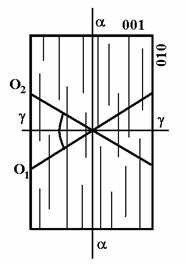
Figure 9 Optical orientation of b-C2S in a 100 plane.
The
exsoluted phase in the form of very small inclusions keeps usually streaming
orientation of polysynthetic lamellae. C2S crystallizes in the form
of round grains, particularly in the case of the rapid cooling. It may have a
fringe-rimmed irregular shape in the slow-cooled clinker. In the case of a coarsely ground limestone, C2S
accumulates into relatively large aggregates - „nests“. Small C2S
grains sometimes line rims of a hexagonal C3S. This is the
manifestation of travertine corrosion, where a melt is subsaturated with carbon
dioxide.
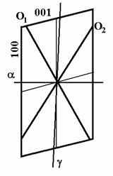
Figure 10Optical orientation of γ -C2S on 010 plane.
C2S
modifications are distinguishable according to a gray-yellow colouring,
opacification, round shapes and above
all to a distinct relief in the penetrating polarized light. In
comparison to C3S, some higher birefringence is distinguishable,
when observing with an analyser and a polarizer (the interference colours are
usually yellow of the 1st order). If comparing the studied dicalciumsilacate
modifications to natural minerals, α-C2S is the most similar to
nagelschmidtite, α´-2S
to bredigite, β-C2S
to larnite and merwinite, and γ-C2S to monticellite. In cement
clinkers, all listed minerals are included under the single term belite
(dicalcium silicate).
Tricalciumaluminate
- C3A - 3CaO.Al2O3,
forms so-called dark interspace matter of cement clinker. Its identification in
thin sections and grain preparations is complicated, because its refraction is
close to the glass phase and more or less to
C2S and C3S, too. In industrial clinkers,
tricalciumaluminate is quite easy to identify according to hypautomorphic
perpendicular cross-sections and its violent reaction with distilled water. It
forms tiny, transparent, colourless crystals imperfectly cleavable on
octahedron. Its microstructure is of the
perovskite-like type. In a solid solution of cement clinker, it may contain a
lot of foreign substances.
A C3A
polymorphism wasn’t unambiguously proved, even despite the fact that according
to some researchers a so-called „prismatic“ phase of clinker may be equivalent
to a metastable C3A modification stabilized by alkali metals. Rarely
a cubic C5A3 (5CaO.3Al2O3)
modification may appear in Portland
clinker.
If alkalis
are not significantly represented in the original material or if the clinker
cooling was very slow, tricalciumaluminate is cubic, isotropic, n = 1.710. If
the content of Fe2O3 in
solid solution reaches 10 %, affect of the increasing Fe2O3 in solid solution contain
causes a rising refraction up to 1.736. The rising refraction value, along with
a microchemical analysis are significant indicators of formation of solid
solutions.
In a thin section,
C3A is colourless, it forms isometric grains with rectangular or
hexagonal cross-section (it reminds of C3S). Clinker cooled in a
standard way is fine-grained, without the presence of oxides of alkali metals.
If the clinker is being cooled very slowly, it crystallizes intensively and
closes inclusions of other silicates, CaO and periclase.
Long
prismatic (lath-like) anisotropic crystals, reaching 10 - 15 microns represent
another C3A form. In penetrating light, their birefringence is weak
and their extinction is parallel. It was verified that this prismatic phase is
formed just in clinkers containing Na2O and K2O.
Therefore it was stated that the prismatic phase is an alkali-stabilized C3A
form. There is usually 5-13 % of prismatic phase present in a normally cooled
clinker. refractions have not been measured yet successfully, the commonly
stated mid-values are n = 1.72, D =
0.005 - 0.015. The mineral is usually opticaly biaxial with a 2V = 52°
mid-angle. Therefore, in penetrating light, it can be even more easily confused
with C3S than the cubic, isotropic modification of C3A.
In rapidly cooled clinker, the prismatic C3A may be totally absent,
alike in the clinker with the aluminate module lower than 1.63.
Brownmillerite
- C4AF or C6AxFy - celite =
tetracalciumaluminiumferrite, 4CaO.Al2O3.Fe2O3.
Brownmillerite is a part of the interspace matter and along with a ferric glass
of the so-called light interspace matter. Its reflectivity and refractions are
of the highest values among the commonly present clinker minerals.
Calciumaluminiumferrites are of a rhombic symmetry and if they are surrounded
with crystal faces, they form tiny prismatic crystals or dendritic
(skeleton-like), salient, high birefringence formations. They are
characteristically brown-yellow. They are distinctly or even significantly
pleochroic in light brown, dark red-brown or yellow-green shades. Because they
crystallize as the last phase, they are usually xenomorphic and they fill
spaces among surrounding calciumsilicates and calciumaluminates. Prismatic
crystals are rare. Their shape is affected
by a cooling speed and by the Al2O3 / Fe2O3
ratio. Having a low value of aluminate module and being cooled slowly, the
crystal shape is short prismatic, the crystals have a significant pleochroism
and they are relatively large. If the Al2O3
/ Fe2O3 ratio is
high, the crystals are small and acicular. Typical dendritic formations are
formed in a rapidly cooled clinker and components of this phase remain in a
heavy reflecting ferric glass matter after rapid cooling.
However,
refractions stated for brownmillerite [α = 1.96, β = 2.01,
γ = 2.04, D = 0.080, Chm(-)] differ from „brownmillerites“ in
common clinker-types. Lower refractions are usually detected, e.g. α = 1.852 + 0.005, β = 1.961
+ 0.005, γ = 2.001+0.002, D = 0.148-0.159. This is one of
the evidence of a solid solution with C3A
or of a rhombic C5A3 which
is microstructurally close to C4AF. In these solid solutions,
refractions may drop down to following
values: α = 1,714, γ = 1,854. On the contrary, a
brownmillerite solid solution with a higher
2CaO.Fe2O3 content has higher refractions
than pure C4AF. E.g. at approx. 10 % 2CaO.Fe2O3 content the refractions increase to
α = 1.98 and γ = 2.08. Such
solid solutions are formed in high Fe3+-content clinkers with the Al2O3
/ Fe2O3 ratio < 0,64. C4AF can further
contain less than 1 % MgO that is manifested by the drop of refractions
refractions, more intensive colouring and pleochroism. An average content of
brownmillerite in clinker varies around 10 %, usually between 8 and 13 %.
A larger
free calcium oxide amount occurs in industrial clinkers due to technological
errors during a production process. The mineral is considered to be an
undesirable admixture. The cause of its formation is a very high CaO content,
imperfect limestone grinding, bad material homogenization, low furnace
temperature or a slow cooling. So it is concerned the unreacted primary free
calcium oxide (I) or in the other case, the free secondary calcium oxide (II)
formed by decomposition of C3S (at the eutectic temperature)
according to the following equation:
3CaO.SiO2
↔ 2CaO.SiO2 + CaO.
Therefore,
sometimes one can find CaO that forms aggregates of isometric orbicular grains.
They occur in a form of inclusions in crystals of C3S and C3A.
Tricalciumaluminates and tricalciumsilicates isolate free CaO (I) from a
remaining melt during the clinker cooling process. In the other case, it forms
very small particles surrounding C3S - free CaO (II) grains along
with C2S. In this case, CaO (II) splits off the tricalciumsilicate
during a slow cooling below 1250°C. Disintegration starts from the
tricalciumsilaicate surface. Besides formation of free lime, content of C2S increases to the exclusion of C3S too. Free
calcium oxide forms small round grains 1 - 5.10-6m sized. They are colourless and isotropic. In thin
sections, they have a distinct relief (n = 1.833 - 1.846).
Periclase -
MgO occurs in clinker in a form of transparent, colourless, skeleton-like up to
automorphic tiny crystals. The crystals are small, cube and octahedron-shaped,
scattered in the interspace matter. Their size reaches 15 - 20.10-6m
in a normally cooled clinker. In a rapidly cooled clinker, it is very fine-grained
and its size reaches up to 3.10-6m in maximum. Periclase has usually
a relatively high thermic expansivity. It takes up a smaller space than the
space, which it was filling immediately after the crystallization. Thus, it is
possible to state that it is „freely placed“ in the interspace matter. Small
cracks are formed around the MgO crystals. They make the relief more
conspicuous and they cause spalling out
of MgO crystals during grinding. Due to its high refraction n = 1.734 to 1.737 and its isotropy, it can
be easily confused with C3S or C3A in the thin sections.
Due to its considerable hardness, it has a distinct salient relief, if
preserved during the grinding and polishing. The periclase content is always
lower then a total volume of MgO. A part of MgO (up to 1%) transforms to C4AF
or to glass matter. Therefore in a slowly cooled clinker, the periclase content
is higher than in a rapidly cooled one, where all MgO may be present in glass
phase.
Glass phase
is a part of the interspace matter. It is usually yellow-green or brown to
black coloured. In a covered thin section, its identification is practically
impossible. It is identifiable using etching in a polished section and in a
polished thin section. Glass phase refraction is variable and depends on its
chemical composition. It varies around n = 1.70 in a high Al2O3
/ Fe2O3 (over 3.2) ratio clinker. The value of refraction
is significantly higher (n = 1,85) in a low aluminate module clinker (e.g.
0.64). The total percentage share of glass phase depends on cooling speed and
oscillates between 0 - 3% in a slowly cooled clinker and between 8 - 22% in a
rapidly cooled clinker.
In Portland
clinker, alkali metals compounds may be present in a form of solid solutions in
previously mentioned silicates or they rarely form separate minerals. In common
clinkers, the content of alkali usually does not exceed 2 % and has a
significant affect on microstructure and mineral composition of Portland
clinker. Oxides of alkali metals concentrate first of all in glass matter. They
may form a solid solution with C3S along with present aluminates and
increase its stability. If sulfate anions are present, separate minerals -
sulfates may be formed. Isometric K2SO4 grains with a
very low birefringence D = 0.004 and with α = 1.493, β = 1.494,
γ = 1.497, Chm (+) are formed first of all. K2O.23CaO.12
SiO2 is formed, if a larger K2O amount is present. Its
outstanding feature is a polysynthetic twinning, α = 1.695,
γ = 1.703, Chm (-). A K2O.8CaO.3Al2O3
compound is formed in a rapidly cooled clinker. Na2O reacts with SO3
more slowly and after K2O. A Na2O.8CaO.3Al2O3compound
with the refractions α = 1.02, γ = 1.710, D = 0.008, Chm
(-) is formed. It is similar to C3A. The alkali compounds
are a part of the dark interspace crystallic matter. In case of their
crystallization the content of free CaO increases.
14.1.1 Identification of clinker minerals using
etching of polished sections and polished thin sections
For
identification of clinker minerals, usage of a lot of agents is being recommended.
Relevant action times are usually listed simultaneously. Reactions proceeding
during the etching process depend on following factors: chemical composition,
compactness, forming conditions of clinker and simultaneously on the
concentration, temperature and action time of etching agents. Therefore, it is
necessary to consider the recommended times of etching to be just informative.
An optimal time of the etching process has to be verified experimentally for
individual cases. Strongly burnt out clinkers from rotary furnaces usually
demand a longer action time of etching agents than the softly burnt out, more
porous ones. An etching agent should be dropped with a small pipette on a
polished thin section (polished section) or the lustre surface should be
immersed into the agent placed in a small flat bowl dish, possibly is
being it should be exposed to the affect of
agent vapours. A relevant time later, the excess volume of the agent is
being sucked out using a filter paper, the preparation is being washed with a
waterless ethyl alcohol minimally twice. The excess volume of alcohol is also
being sucked out.
Success of observing of etching tests done on
the polished surfaces depends on a quality of the polished surface and also on
a perfection of degreasing. Due to hydration, the polished surface looses its
luster if it was prepared long time before the etching tests. Repolishing with
micropolite on velvet is then recommended. Storing of preparations in
desiccator is suitable. A clinker microstructure is usually being evaluated
along with individual mineral phases.
The percentage share of clinker minerals and the uniformity of their
distribution, their size, development, shape, mutual relationships of crystals,
size and number of pores etc are watched.
The
characteristics often depend on the place of collecting of the studied sample.
There are differences between a surface
and an interior part of a sample. Differences of mineral composition between
the surface, aproximately 5 mm thick, layer and
the interior part of clinker have
often been observed. The exterior part is usually rich in C2S, the
interior one contains more C3S.
The C3S degradation in the
surface layer has been explained in a connection with an affect of a
non-equilibrium melt that reacted with C3S. This reaction leads to
the formation of β-C2S. It is suitable to correlate the
microscopically assessed modal composition of clinker with the results of
calculations of equilibrium-state normative chemical analysis.
Differences
of individual assessments are considered to be a criterion of equilibrium and
they complexly reflect a complete manufacturing process: mineral composition,
homogenity and material fineness, burning out temperature and cooling
conditions.
Periclase
is the easiest identifiable mineral in a polished thin section. It usually
occurs in a form of very small, angular grains with a positive relief. Further,
round grains of free lime with a feeble negative relief having a white to
greyish reflection are observable. The free lime soon becomes darker, due to a
reaction with air humidity. The free lime usually occurs in clusters.
Water is
the least intensive clinker etching agent. CaO and C3A (the dark
interspace matter) are being etched for 1-3 seconds. C2S, C3S
and glass matter with low content of iron become corroded after a longer (5 -
20 seconds) affect of an etching-agent. After the longer etching-period, C3S
becomes darker than C2S.
After a
short (2 - 5 seconds) etching with water, it is convenient to go over to
etching with 1% HNO3 ethanol solution (for 2 - 5 seconds) or 1 % NH4Cl
water solution (for 10 seconds) to make free CaO and C3A more
conspicuous. The affect of the second agent is stronger than the commonly
recommended first one‘s. Polygonal, first comming out, tiny alite crystals
differ from later comming out round belite grains that keep a lighter reflexion
shade in comparison to alite. They are being etched less intensively. Alite
gets significatly darker after a long period of etching. In the interspace
matter, C3A is dark, usually prismatic. Its shade is similar to the
irregularly bordered glass matter with low content of iron, which significantly
differs from the light reflecting phases - C4AF and a ferrite phase.
Instead of
the above proposed way, one may use 0,25 - 1 % solution of icy acetic acid
dissolved in ethylalcohol (2 - 60 seconds period of etching) for the etching
first, or 1 % HNO3 solution
in isoamylalcohol (2 - 15 seconds). CaO, MgO, C3S, C2S
become more conspicuous and C3A becomes distinguishable from the
light interspace matter. Alite is being etched more intensively than belite and
thus it is less reflective - darker. Sequence of the effect of acetic acid on individual clinker
minerals is following: CaO, C3S, MgO, C2S, C3A
and C4AF. On the contrary, belite is darker, alite is gray-blue and
C4AF stays light, a low ferrite matter is dark when using 0,5 N HCl
(for 5 - 10 seconds).
10 % KOH
water solution at 29-300C temperature (for 15 seconds) is being used
to recognize the light interspace matter after usage of acid etching agents. So
the Fe-rich acid agents resistent glass matter differs This is the way to
distinguish Fe-rich glass matter, which is resistant to acid agents from C4AF
in the rapidly cooled clinker. Due to KOH effect, the glass mater becomes
darker, but brownmillerite stays light reflective. This is not the only way of
identification. Except of the above mentioned sequence of the etching
procedure, one can use other agents to identify individual phases (see Table
2). To make C3A more conspicuous in the interspace matter, polishing
with 10 ml of a N-oxalic acid in 50 ml
of 95 % ethylalcohol solution (for 5 - 15 seconds) after a short-time etching
with HNO3, is recommended. After this procedure, C3A
reflection becomes red-brown, reflections of the other clinker minerals do not
change. After etching with CH3.COOH
or HNO3, usage of a 10 % MgSO4
water solution is possible. So, alite, which is dark gray, is
distinguishable from light gray belite this way. In a similar way, it is
possible to make alite more conspicious by etching with ammonium sulphide (for
5 - 30 seconds). Dark gray to blue C3S is intensively etched, while
belite stays light. Following etching with a 1 % HNO3 alcohol
solution makes belite more conspicuous too. Before usage of polysulphide,
etching with water is recommended to make free lime more conspicuous. This
method is particularly useful to distinguish secondary, fine-grained CaO and C2S
from remains of primary C3S (from which they were formed by decomposition
under 1250°C). Secondary C2S
and CaO may rarely pseudomorph completely the original C3S hexagonal cross-sections. It
is possible to make C2S more conspicuous against C3S by a
HF-vapours affect (for 30 seconds). Originally, belite (C2S) is
yellow to orange and during the effect of HF its reflection shade becomes green
to blue. In a grain preparation, according to Astrejeva (1959), C3A
is identifiable by colouring the preparation, previously etched with 0,1 N HCl
(10-15 seconds), with the patent blue (pale acid blue 3). After etching with
HCl and colouring, the preparation is being washed with a waterless alcohol.
The other clinker minerals do not become coloured, so it is possible to do a
quantitative analysis too.
In the
grain preparation, it is possible to assess the free lime volume by a
microchemical reaction using the White’s Agent.
The agent consists of 1 g of phenol dissolved in 3 ml of
nitrobenzene with one drop of added
distilled water. It reacts with CaO
within 10 minutes along with the formation of long columnar or acicular calcium
phenolate crystals. In the CPL, the crystals display various interference
colours, while they are almost indistinct in the PPL (due to their refraction
similar to the White’s Agent’s one). In this solution, reliefs of fragments of
clinker minerals are the most distinct ones. The White’s Solution reacts with
Ca(OH)2 a longer time later (after approx. 20 minutes or more ).
Table 9 List of etching agents and their affect on
clinker minerals.
|
|
Etching
agent |
Period of
etching |
Temperature
of etching |
The
affect on succession of clinker minerals according to the intensity of
etching |
|
Acid
etching agents |
1% HNO3
amylalcohol |
2-15 sec. |
20°C |
CaO
silicates |
|
|
1% HNO3
ethylalcohol |
5
sec. |
20°C |
CaO
silicates aluminates |
|
|
1%
ice-cold acetic acid in ethylalcohol solution |
2-5 sec. |
20°C |
CaO C3S
MgO |
|
|
10 ml of
oxalic acid in 50 ml of 95%
ethylalcohol solution |
5-15 sec. |
20°C |
aluminates |
|
|
1% H2SO4
in alcohol solution |
- |
20°C |
Aluminates
Non-differentiated interspace glass matter |
|
|
HF
couples |
- |
20°C |
Changes
colour of C2S |
|
|
H2O |
5-10 sec. |
20°C |
CaO
aluminates |
|
Acidic
water-based etching agents |
Concentrated
fluorhydric acid watter-based solution |
2-3 sec. |
20°C |
C2S
and ferrites |
|
|
1:10
fluorhydric acid water solution |
30-60
sec. |
20°C |
C2S
and ferrites |
|
Alkali
water-based etching agents |
1% borax
solution |
10 min. |
20°C |
CaO and C3S
pentacalciumaluminate |
|
|
1% borax
solution |
10 min. |
20°C |
CaO and C3S
pentacalciumaluminate |
|
|
8ml of 10%
Na(OH) +2ml 10% Na2HPO4 solutions |
1 min. |
50-55°C |
Everything
except of dicalciumferrite and dicalciumsilicate |
|
More
etching agents following one after another |
H2O, then solution of 1% HNO3 in
ethylalcohol |
2 sec. 3
sec. |
20°C |
CaO, MgO,
„dark“ crystallic and glass intergranular matters silicates |
|
|
H2O, then solution of 1% HNO3 in
ethylalcohol |
3 sec. 3
sec. |
20°C |
CaO, MgO,
„dark“ crystallic and glass intergranular matter silicates |
|
|
then 10%
KOH water solution |
15 sec. |
30°C |
Light
intergranular matter |
14.2 Aluminous
cement
The
aluminous cement was preared by Biede in France in 1908 for the first time. It
is made of pulverized bauxite and limestone mixtute [1:1ratio]. There are two ways
of its preparation. Either a firing to the sintering point [1350°C] - sintered aluminous cement or a high
temperature melting (e.g. in electric zigzag kilns) - electrocomelted aluminous
cement. The aluminous cement significantly differs from the Portland cement.
The difference is that the aluminous cement contains calciumaluminates. On the
contrary, the base of the Portland cement are calciumsilicates. The calciumsilicates are undesirable in the
aluminous cement.
The
chemical composition of the common aluminous cement for construction purposes
(under 50 % A12O3)
may fluctuate in a certain range. The
content of individual oxides usually
fluctuates in ranges: SiO2 5 - 15 %, Al2O3 35
- 50 %, Fe2O3 5 - 15 %, TiO2 1,5 - 2,5 %, CaO
35 - 45 %, MgO 0,1 - 1,5 %. Its mineral composition has a direct relation to
the content of oxides. Calcium aluminates prevail over silicates.
We differ:
- primary
phases: monocalciumaluminate CA, a basical component, very active concerning
hydration, up to 65 % ;
- secondary
pheses: dodekacalciumheptaaluminate C12A7, very active;
calciumdialuminate CA2, medium active; gehlenite C2AS,
slightly active in a crystallic form, active in a form of a gehlenite glass
that rather corresponds to melilites; C6A2F-C2F,
listed mostly as brownmnillerite C4AF, active; dicalciumsilicate, C2S,
little active;
- other
phases: C2(F,M)S, possibly C6A4(F, M)S,
pleochroite; CaS that forms in a reduction environment, CF2,
possibly CF, calciumdiferrite or ferrite; FeO, Fe3O4,
possibly another phases (e.g. CT).
To make the
picture complete, it is necessary to add that mineral forms of iron oxides have
not been completely surveyed yet. Their character
depends on the environment where they formed.
Monocalciumaluminate
- CA - CaO . Al2O3
crystallizes in a monoclinic symmetry. If it forms in a solid phase reactions,
it usually forms short prismatic crystals. These are cyclic coupled in cuts
parallel to a basal face, the cross sections are pseudohexagonal. When it forms
from an eutectic melt, it is fine-grained and usually accompanied by a
simultaneously formed gehlenite.
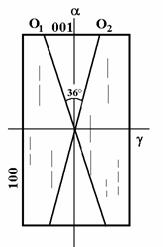
Figure 11 Optical orientation of monocalciumaluminate in
the cut according to 010.
It is
usually bounded with crystal faces, it is rarely xenomorphic. The crystal rims
are sometimes fringed. It is pellucid, significantly cleavable in the
elongation direction according to (110). Refractions: α = 1.641, β =
1.655, γ = 1.661-1.663, D = 0.020.
The optical orientation - see Fig. 4. It formes solid solutions with monocalciumferrite CF in an oxidative
atmosphere and the refractions rise to α = 1.66 - 1.70, γ =
1.68 - 1.72. In the aluminous cement, it is a reactive mineral, its contant
fluctuates between 4% and 61 %, usually
between 25 - 40 %.
Pentacalciumtrialuminate
- C5A3 (now C12A7) occurs in
two modifications. Their formation is affected by oxidative or reduction atmosphere. It is an
undesirable product, because it makes a cement hardening faster. It usually occurs in smaller amounts than CA.
The α
- modification is stable at a normal temperature, crystallizes in an isometric
symmetry. It is usually itense green and forms round, xenomorphic, perfect
isotropic grains without cleavage, n = 1,600 – 1,626, during a manufacturing of
the aluminous cement in a reduction atmosphere. The green colour dissapears if
warmed in air and the refraction is 1.608.
The a´- modification
is unstable at a normal temperature, crystallizes in a rhombic symmetry. In the
aluminous cement it forms in an oxidative atmosphere. It forms acicular, long pillar-like and possibly
lamellar crystals that sheaf-like or spherolitic agglomerate. Their pleochroism
is characteristic - in the X-direction it is blue-green, in the Z-derection it
is olive gray. Mg presence leads to a change of its pleochroism. The colour
changes to light or even dark violet. Its refractions are α = 1.617, γ = 1.634 -1.692, D =
0.017 - 0.065.
Monocalciumdialuminate - CA2 (earlier
tricalciumpentaaluminate) - CaO.2Al2O3 occurs
rarely and only in the aluminous cement. The crystals are long prismatic to acicular.
It crystallizes in a monoclinic or a tetragonal symmetry. The mineral has a
characteristic high birefringence D = 0,035. The refractions: α =
1.617, γ = 1.652, Chm (+). The cleavage has not been
observed.
β -
dicalciumsilicate
is usually present in the intergranular matter among crystals of CA along with
gehlenite and C12A7.
It forms very small grains. In thin sections, it is distinguishable
according to its higher refraction that conditions a distinct relief and
according to its higher birefringence. It is usually represented only
marginally. Optical characteristics are given above.
Fig. 5 Chart of a dependance of optical
characteristics on a chemical composition in an äkermanit-gehlenite isomorphic
series.
Gehlenite
- C2AS -
2CaO.Al2O3.SiO2 represents a common component
of the aluminous cements. If the SiO2 content in the material is
higher, there can be up to 40 % of
gehlenite present in the final product. The mineral is not hydraulic and its
presence is undesirable. CaO and Al2O3 that would
otherwise form hydraulic calciumaluminates enter the mineral microstructure. It
forms short prismatic crystals with square lateral and oblong longitudinal cross
sections, possibly xenomorphic grains.
It is pellucid to ligh bluish, sometimes zonal and skeleton-like;
α = 1.658, γ = 1.667 - 1.670, D = 0.009 - 0.012. Values of the optical constants vary
according to a composition of solid solutios (see Fig.5) which gehlenite forms
with a series of oxides. A cleavage
according to {001} is well distinct, the cleavage cracks are perpendicular to a
crystal elongation. It differs from a similar calciumaluminate, which has a
close refraction too, by significantly lower birefringence and an inverse
orieotation of cleavage. Gehlenite is usually one of the basic components of
the matrix or it forms intergrows with prevailing calciumaluminate crystals.
Perovskite - CaO.TiO2 - occurs in the aluminous cement very often. It crystallizes in a rhombic
symmetry. It has a high relief, n = 2.34 - 2.38, it is weak birefringent,
scattered in a form of fine, often skeleton-like crystals in
matrix. Iron can be bound to
brownmillerite and calciumferrite., magnetite Fe3O4 or
wűstite FeO forms during an oxidative burning or in reduction conditions. A smaller amount of iron deoxidates to a
ferrosilicon in a zigzag kiln.
It is
possible to determinate the mineral composition of the aluminous cement a
similar way as the Portland cement, in grain preparations, polished thin
sections and by etching tests too. The identification is easier in the case of
melted samples that are coarser crystallic than the clinker ones. In both
cases, CA, C12A7 and C2AS distinguishing
according to a hight of birefringence and based on a development of crystals is
the most convenient. CA or C2AS
forms a coarser grained phase called phenocrysts, the other minerals form fine
grained intergranular matter according to a composition of the cement. C12A7
is typically green if observed in PPL. A CA presence test may be done
using an immerse liquid with n = 1.652 - 1.657. It corresponds to mid-values of
α and γ of CA, if
the liquid doesn’t contain CF in a solid state. If there is some mineral with
birefringence higher than a value corresponding to CA present, it is suitable
to do a test of presence of CA2. We use an imerse liquid with n =
1.630 - 1.640. A test of presence of
free CaO using the White’s solution is
necessary in the case of a clinker aluminous cement. In polished sections and
thin sections, etching of CA at 20°C for an hour for an identification is
recommanded. (C2AS is etch-resistant), for etching of C12A7
using of water at 100°C for 10-15 min. or 1% borax water-solution at 100°C for
30 seconds is recommended. For an identification of C2AS 2 % NH4Cl
and 2 % Na2HPO4 . 12H2O water solution at
100°C for 3-5 minutes.
An air
lime for mortars
and plasters and plasters preparation should be prepared by calcium carbonate
(calcite) burning.
The calcium
carbonate decomposition during its burning proceeds according to an equation:
![]()
During a
burning of a pure limestone containing just calcium carbonate, 56 parts of
calcium oxide and 44 parts of carbon dioxide form 100 parts of original
material. 422 kcal of heat is necessary to decompose 1kg of CaCO3.
The decomposition of magnesium carbonate proceeds according to a similar
pattern: 310 kcal is necessary for a decomposition of 1 kg of MgCO3 ( Králík, Fojtík 1972).
The air
lime slakes at a contact with water and calcium hydroxide (slaked lime) forms
according to an equation: ![]()
The slaking
proceeds very rapidly along with a heat releasing.
According
to a amount of water one can gain:
- Dry hydrate (at small water amounts,
so - called dry slaking);
- plastic lime paste (with a 230 - 300%
of a soft water excess).
According
to a chemical composition we differ:
- pure lime (with the content of CaO > 90%
and MgO < 7%)
- common lime (with a CaO contant ranging 85
- 90% and MgO < 7%)
- dolomitic lime (with the content of CaO +
MgO > 80%, the content of MgO should be
> 7%)
Table 10 General scheme of manufacturing and processing
of lime.
|
Technological
component |
Chemical
scheme |
Microstructural
scheme |
|
Limestone,
dolomitic limestone |
CaCO3,
possibly a mixture of CaMg(CO3)2, contaminants: content
of Fe2O3, Al2O3
and so on |
Microstructure
formed by crystals of calcite (sparite, micrite), possibly dolomite, clay
minerals an so on. |
|
Crushing,
sorting |
No
changes |
Mechanical
disintegration and formation of a grainy (dispersion) mictorstructure |
|
Burning
at 1100-1300oC |
Decarbonation
by releasing of CO2 from the mixture |
Disintegration
of the original microstructure |
|
Lump
lime, ground lime |
CaO,
possibly MgO too, contaminants in compounds |
Formation
of a new microstructure, composed of grains (crystals) of CaO, possibly MgO
and other phases, numerous pores |
|
Water
addition |
H2O |
Disintegration
of the previous microstructure, transformation to a plastic mixture |
|
Calcium
hydrate, lime paste with a water excess |
Ca(OH)2,
possibly Mg(OH)2 and H2O |
Formation
of new phases, mostly grains and crystals of portlandite(Ca(OH)2 |
|
Filler
addition (aggreggates) |
Variable
chemical composition, does not take part in any chemical reaction |
Inactive
grains of variable size |
|
Water
addition |
H2O |
Formation
of a plastic mixture |
|
Mixing
and using for a certain purposes |
Carbonation
of hydroxide Ca(OH)2 by air CO2 |
A colloid
dry shrinkage and carbonation - micrite of
the plastic mixture |
|
Hardened
solid product - mortars and plasters, plaster etc. |
CaCO3
and a chemical filler of variable composition |
New
formed microstructure composed of grains of inactive filler and CaCO3 micro crystals joining the
grains of the filler together, a
presence pores is characteristic |
The problem
of the formation of solid lime mortars and plasters or plaster includes three
processes:
- An
exsiccation of a lime suspension accompanied by a mortars and plasters
shrinkage along with a formation of a compact mass;
- A
formation of a solid calcium silicate phase by quartz dissolution in an
alkaline environment of calcium hydroxide;
-
Carbonation - includes a processes of a chemical conversion to calcium
carbonate (see Table 5).
A friction
process has the most significant affect on a strength of lime mortars and
plasters. A mixture of a lime cement and a gauge water (along
with soluble alkaline calcium silicates) fill pores among aggregates and the
mortars and plasters. Calcium carbonate forms due to air carbon dioxide.
Calcium carbonate microstructure corresponds to micrite. A speed of carbonation
is the highest at a relative air humidity ranging 50-60%, it does not proceed
in a dry environment at all. The process almost stops at a higher relative air
humidity due to a difficult CO2 penetration through the porous
system filled with water. An originally high alkalinity of fresh mortars
and plasters (stated pH values 12,5 - 13,5) gradually drops to a value of pH
approx. 8. It is possible to say that the lime mortars and plasters strength
depends on a partial pressure of CO2 (its normal ratio in the air is
about 0,03%), on an amount, species and
degree of the lime slaking (the unslaked lime accelerates the hardening
process, but „blocks“ the CO2 penetration to the center of mortars and
plasters), on a porosity of mortars and plasters (given as a water coefficient,
cement/aggregates ratio, a size of sand grains and their distribution curve)
and is determined by a moisture and temperature of atmosphere too.
A
microcrystallic carbonate (sparite) appears (first in a porous system of
mortars and plasters and subsequently in cement) due to a partial dissolution
and following recrystallization of micrite. A share of sparite increases with
time. However its increse is not linear, but depends on a series of
factors.
A
degradation (ageing process) of mortars and plasters runs at a presence of the
air humidity (or as a result of capillary action of water, rain and snow
affect, a placing of mortars and plasters in a construction in various cardinals
points, at various hight levels, in places with a permanent moisture or with
its cyclic changes). The process manifests as a slower dissolution of
micrite and a graduate enlarging of calcite crystals - the sparite formation
first of all. A long-term study
of mortars and plasters and plasters verified that these process runs faster.
E.g. the process is faster in mortars and plasters and plasters prepared by
slaking of an imperfectly burnt lime than in mortars and plasterss made of a
perfectly burnt one. A crystallization pressure of authigenic calcite crystals
(which are already microscopic according to a place of their formation) leads
to a strenght decrease of mortars and plasterss and a follwing damping off of the masonry face.
Physical
and optical properties of calcite are listed in the encyclopedia of
minerals.
Gauging
gypsum mortars and plasters belong to a group of air mortars and plasters. Calcium carbonate forms
a base of these cements. The gypsum mortars and plasters represent rather widespread
group of cements.
A strenght
of hardened suspension made of gypsum with a prevailing contant of hemihydrate
CaSO4.0,5 H2O is an important criterium for its
application. The hardening process of gypsum is characterized by a reabsorbing
of water and a recrystallization to dihydrate.
0,18g of
water is necessary to transform one gramme of hemihydrate to a solid phase,
i.e. it gets transformed to gypsum. If there is more water in the suspension,
it stays unreacted among dihydrate crystals in pores. The water evaporaters
after the hardening and it leaves a continuous pore-net.
A strenght
of hardened gypsum suspension depends on a misromicrostructure of the hardened
product, on qualitative and quantitative parameters of the microstructure. A
formation of this microstructure is a function of series of variables. These
are partly internal ones, material, e.g. composition of gauging plaster, water
coefficent, additives etc., partly external ones, to which belong e.g fineness
of grinding, temperature of water, time and intensity of stirring.
Dihydrate
CaSO4.2 H2O occurs as a natural gypsum and on the other hand as a product of
hydration of gypsum. The natural gypsum is rather compact material with a relative
low porosity (its physical and optical properties are listed in the
encyclopedia of minerals). An aggregate composed of small acicular crystals is
a product formed by the process of hydration. The crystals are irregularly
orientated, they can be feltlike and partly adherent. An average lenght of
crystals reaches n.10-6m. A certain amount of dry hydrate is added
into the gypsum in some cases. In this case, a micrite calcite occurs besides
the acicular crystals of gypsum. The micrite calcite is translucent, brownish
and sometimes makes an identification of the gypsum mortars and plasters more
difficult. The gypsum recrystallization occurs with a proceeding
process of ageing in suitable climatic conditions. Size of individual crystals extends and their
identification becomes easier.
Microscopic
study of hydration and identification of products is extremely complicated by a
small size of authigenic crystals. An electron microscopy is more convenient
for studying them. For a petroligical microscope study, using of modelling of
conditions and turning some away from a common routine is necessary to get
largeger observable products.
For the
study, we use identification in grain preparations, thin sections, polihed thin
sections and polished sections again. Before grinding, a sample should be dried
at 120-125°C for 6-15 hors. Afterwards,
an adsorbed water shoud be removed, the sample should be consolidates by
boiling in the Canada balsam (or in the epoxide resin) and ground without
water. A waterless alcohol or glycerine, kerosine or oil shoul be used. A thin
section thickness should range 15 - 30.10-6 m.
Using the
thin sections one can determinate a percentage of non-hydrated grains and their
size, type of porosity, size and distribution of pores, mutual relations of the
original and authigenic cement phase, compactivity and formation of authigenic
forms.
In a
normally set cement, one can with difficulties identify pellucide, porous,
matrix with non-hydrated residuum of clinker minerals: C2S, less often C3S and
C4AF too and crystals of birefringent lamellar portlandite Ca(OH)2
. Ca(OH)2. In normal conditions of hydration, portlandite
occurs in a form of small hexagonal tables. The porosity of gels extends with
an increasing size of cement grains and water coefficient. A gel usually fills
small canals and pores, which are smalled than
1.10-6m. It may occur in larger pores too and as well as
Ca(OH)2, it can rim graines of cement clinker. The gel
looses its homogenity and isotropy and recrystallizes. A crystallic, usually
grainy phase occurs. However, the crystallization proceeds very slowly. In a
polished thin section, one can differ pellets of the primary clinker and Ca(OH)2 by tinging. Using
of a solution of alcohol methylene blue with an addition of benzoic acid or an
alcohol solution of naphtol green is the most common. Only the gel gets dyed.
Using
polished thin sections and polished sections, one can identify a ratio of
non-hydrated cement pellets too. The pellets are
distinguishable according to their distinct positive relief for the first
sight. It is suitable to make a repolishing before the application of chemical
agents. A shammy leather and SnO2 should be used to decrease a
spalling out. Before the polishing, the products of hydration should become
more conspicious due to an affect of the alcohol patent blue. The
non-hydrated cement is colourless after the polishing. In the cement pellets, rims
of tricalciumsilicate and dicalciumsilicate get emphasized by etching wiht HCl
dissolved in alcohol (a drop of concentrated HCl per 10 ml of alcohol) during
three seconds.
If using
the grain preparations, before the observation itself, a separation of
unreacted pellets from hydrated phases must be done. One can
realize it by a soft knocking and pulverizing the sample in an agate bowl. The
fine part should be separated with a sieve with an opening range 40-60.10-6m.
One uses a n = 1,67 immersion liquid to differentiate a higher refractive
unhydrated cement from a lower refractive hydrated products too. A Ca(OH)2
presence can be proved by the White‘s test at the temperature of 40°C (the reaction speeds up). It is
possible to determinate a medium refraction value of the hydration products by
the immersion method. The hydration products are too fine-grained to realize
a measurement of orientation of the individual grains. The most distinct
autigenic mineral of hardened mortar, plasters and concretes is calcite.
Calcite forms by a reaction of air carbon dioxide with Ca(OH)2.
Ca(OH)2 gradually releases during the hydration of clinker
phases. On the first stage, a fine-grained micrite forms. Due to their high
birefringence, its fine particles mask low birefringent products of hydration.
A study of
the hydration process of cement clinker
should be done using a fine-dispersive powder with a maximum size of
grains ranging 30-40.10-6m. The material should be wetted by water
to form as large hydrated crystals as possible. The hydration
process of the most common used clinker minerals is summed up in Table 3. A
clinker of the Portland cement has been chosen as an example, because the
Portland cement belongs among the most produced cements worldwide. Before its
application itself, it is being special-purpose modified using various
correction materials. According to them one comes across various cement types:
- high
initial strength cements;
-
sulphate-resistant cements;
- road
cements;
- white
cement, colour cements;
- expansive
cements;
-
plasticized Portland cements;
- strontium
and barium cements etc.
These
correction components (with an exception of gypsum) are not included in the
following list.
Table 11 Hydration of individual components of the
Portland cement.
|
C3S
(3CaO.SiO2) 2C3S+6H®C3S2H3+3CH
2C3S+7H®C3S2H4+3CH
|
The
reaction is not stoichiometric, because a hydro silicate gel of the C-S-H
phase (RTG amorphous) with a fluctuating composition forms. The basic reaction
of the cement hydration and the formed product of the C-S-H phase is a
carrier of a majority of properties of the hardened cement. |
|
b-C2S (b-2CaO.SiO2) 2C2S+4H®C3S2H3+CH |
The
reaction is very slow. |
|
C3A
2C3A+21H®C4AH13+C2AH8®2C3AH6+9H hexagonal ® cubic hydrate C3A+CH+12H®C4AH13 |
The reaction is fast. At the presence of Ca(OH)2 and
at a lack of gypsum, the reaction can be the reason of a „false
cement-hardening“. |
|
C3A
at the presence of gypsum C3A+3CS*H2+26H®C6AS*2H31-32
(ettringite), 1-st stage of reaction sometimes Ca6A4(SO4)3(OH)12.26H2O
C6AS*2H32+2C3A + 4H®3C4AS*H12
(monosulphate), 2-nd stage sometimes proceeds [Ca2Al(OH)6].[0,5SO4.3H2O] the
conversion of ettringite to monosulphate may proceed this way too: C6AS*2H32+2C4AH13® 3C4AS*H12+2CH+20H |
The
principal of slowing down of hardening of the Portland cement. The reaction
at the beginning of a contact of the Portland cement with water: S*=
SO2 |
|
Ferritic
phase C2AF+2CH+11H®C4(A,F)H13 C2AF+CH+3CS*H2®C6(AF)S*3H31-32
(analogical to ettringite) C6(AF)S*3H31-32+2C4(A,F)H13®3C6(A,F)S*H12+2CH
+ 20H |
|
|
Free CaO,
MgO C+H®CH M+H®MH |
Accompanied with an expansion, instability
of the cement volume a long-lasting instability of the cement volume, slow long-lasting
reactions. |
A hardened
cement paste (cellular concrete) has a fine-porous microstructure, which
affects its properties: strength, permeability and resistance to an aggressive
environment.
There is a range
of methods to identify a porosity of the hardened cement paste, mortars and
plasters or concrete. These are for instance:
Hg-porositometry, water vapour adsorption or optical methods
(technological pores).
Chosen
properties of some products of hydration of the Portland cement are listed in
Table 4. As shown above, it is apparent that it is almost impossible to study
the aqueous mineral phases of the Portland cement using an optical
microscopy.
Table 12 Properties of chosen aqueous products of the
Portland cement.
|
Phase |
Density |
Crystallization |
Morphology |
Size of
crystals |
|
C-S-H |
2,3-2,6 |
Very low |
Acicular |
0.1.10-6
m |
|
|
|
|
Gel |
<0.01. 10-6 m |
|
Ca(OH)2 |
2,24 |
High |
Lamellar,
pillar-like |
0.01 -
0.1 mm |
|
Ettringite |
cca 1,75 |
Good |
Long,
thin acicular |
10.0.5.10-6
m |
|
Monosulphate |
1,95 |
Medium |
Thin
hexagonal plates |
1.1 -
0.1.10-6 m |
A survey of
various forms of concrete deterioration is given in a work of Matoušek, Drochytka (1998) aimed at an
atmospheric corrosion of concrete. Therefore, characteristic features of the
concrete deterioration, which we are able to identify with a polarizing or a raster
microscope, are only synoptically summarized in the following chapter.
An affect
of CO2 is the most surveyed one. A concentration of atmospheric CO2
is usually 0,03% vol., which corresponds to circa 60 mg of CO2 per
1m3 of the air. The corrosions that is in progress is called
carbonation (a product of a decomposition of lute is calcium carbonate, i.e.
carbonate).
A concrete
gas and vapour permeability (ergo its permeability) depends on a number, size,
shape, configuration and mutual connectivity of individual pores. A total
concrete porosity consists of pores of lute and aggregates and larger cavities
formed as a result of an improper processing of mixture, e.g. exsolution of
aggregates and a cement mixture.
The lute
contains gel pores and micro pores that if constantly filled with water (or
solutions) are practically gas proof. The other pores filled with air, are
permeable for gases. These mostly take part in the concrete corrosion. Gases
and vapours spread by diffusion, i.e. very slowly, in the concrete stone as
well as in every porous material. The diffusion speed affects a
depth, which can be reached by carbon dioxide in the concrete a certain time later. At suitable conditions,
the depth of carbonation of a common more permeable concrete reaches up
to 9 mm after one year and about 20 mm after 10 years.
It is
possible to express chemical reactions running during the lute carbonation by
a following scheme:

The
carbonation of the intermediates possibly continues, e.g..:

The scheme of
the process of carbonation illustrates transformations of basicl products of
hydration of cement with carbon dioxide. A
moisture takes an important part in the carbonation reactions. Four stages have
been specified in the process of carbonation.
In the first
stage, calcium hydroxide transforms to calcium carbonate in intergranular
spaces (the size of the formed product corresponds to micrite) and the pores
become partially filled. The concrete properties are of higher quality in this
stage. In the second stage, other transformations of the products of the cement
hydration proceed. CaCO3 modifications form along with an amorphous
silica acid gel and stay in pseudomorphs after products of hydration of mortars
and plasters, possibly formation of micrite follows again. Sparite occurs just
sporadically. The concrete properties do not significantly change during the
second stage of carbonation. The outstanding feature of the third stage is a
graduate recrystallization of micrite. Sparite (calcite, aragonite) forms along
with it. The concrete mechanical qualities worsen. The fourth stage is
characteristic by a formation of sparite in such a rate that sparite replaces
the lute microstructure. The process is accompanied by a loss of strenght and
cohesiveness.
A moisture
affectst the carbonation speed. If the concrete is dry, the carbonation process
stops. The carbonation is the most dangerous, if atmospheric acid-forming
gasess penetrate up to a reinforcement. Actually, a value of pH of the intergranular solution rapidly
decreases due to carbonation, a reinforceing steel looses its pasivity and
starts to grow significantly rusty. This
already proceeds in the second stage of carbonation. The corrosion proceeds so
fast in the third carbonation stage that the reinforcement and hereby the
whole construction often serves out sooner than the fourth stage of carbonation
starts.
Minerals
formation during carbonation (calcite, vaterite and aragonite) are
characterized in the followig part of the text.
Another
process leading to a desintegration of concrete is sulphatation. In comparison
to carbonation, the concrete sulphatation is much more agresive precess. In a
cellular concrete, air SO2 reacts with hydrated cement products,
possibly with calciumhydrosilicates. At a suitable humidity the decomposition
reactions run immediately. The humidity affects a speed of the reaction, a
quantitative share of final products and intermediates (a concentration of SO2
and time of its attack play a role too). One may document the reaction in
a following form:
 .
.
The
decomposition of calciumsilicates and calcite proceeds in several steps.
Calcium sulphate hemihydrate is an important intermediate, which directly or
secondarily becomes oxidized to gypsum during a following corrosion. A humidity
presence is crutial for the process. About up to 3% vol. of humidity only
sulphate hemihydrate forms and calcium sulphate hemihydrate forms from it
during a following corrosion. Calcium silicate hemihydrate finally transforms
to dihydrate due to another affect of the enhanced humidity. The final product
of the sulphate attack on concrete is always gypsum. Gypsum forms new
microstructure of crystal druses of a significant volume.
Not only
environment and geological bedrock affect the
process of pathological changes, but it is obvious that the deterioration
proceeds in a different way in the case of a Portland clinker concrete, a wite
and a clour clinker concrete, a steel concrete and an aluminous cement. A character of the used aggregate is very
important too. The last sort of deterioration is connected with it. It is
represented by alkali-silicate reactios (ASR) or according to other authors
alkali aggregate (aggregates - crushed gravel) reactions (AAR). The mechanism
is explained according to a scheme shown in Table 13.
Three cases
are usually given for a reactivity of aggregates with alkali:
-
Alkali-siliceous reactions (ASR, AAR);
-
Alkali-silicate-siliceous reactions (ASSR);
-
Alkali-carbonate reactions (ACR).
The
reaction of alkali and aggregates containing various reactive forms of silicon
dioxide: opal, hornstone, flinstone and chalcedony or tridymite, cristobalite
and volcanic glassess (e.g. some hornstone gravels can already cause a decrease
of quality of concrete if they are present in amounts ranging 1-5%). A concrete
manufactured using this aggregate is liable to a very fast disintegration due
to a relative fast expansion along with a formation of alkali-silicate
expansive gels. After expiration of
approx. 10 years, cracks start to exhibit in the building construction.
Reactions
of alkali with tectonically deformed quartz. We sort a wide range of rocks
containing tectonically deformed quartz, which is a strong reactive component
of concrete as well, into this group. The tectonically deformed quartz occurs
in greywackes, argillized rocks (graywackles, arcoses), in some types of silica
sends, quartzites, metaquartzites, contact hornstones, gneisses, cataclased
granites up to mylonites, fylites and arcoses.
The given type of reaction is
characterized by a slower expansion start. The cracks need not to be
perceptible for a more than twenty-year period afrer building up the
construction.
Alkali-carbonate
reaction. It is a reaction of alkali that occur between dolomitic
limestones with a clay addition and alkali pore solutions in concrete. The
reaction is expansive and causes an intense cracking of concrete. So-called
expansive dolomitic limestones are usually formed by a fine grained
matrix. The matrix is formed by micrite and clay minerals. There are dolomite
rhombohedrons scattered in the matrix. This reaction manifests quite soon in
building constructions and the cracking starts after approx. 5 years after
finishing the labour.
Alkali-silicate
reactions can be caused by a composition of a geological bedrock beneath the
buiding. However, a formation of gels does not terminate the process. In a
presence of sulphate anions, new mineral phases of ettringite and thaumasite
gradually occur in a place of gels. Their crystallization pressure leads to a
total concrete disintegration. Characteristics of the minerals are given
below.
Table 13 Mechanism of the alkali expansion
|
|
Alkali
distribution (comming from a cement or certain aggregate pebbles, e.g.
feldspars in a concrete-water mixture) |
|
||
|
|
Reactions
of alkali solution (Na2O, K2O, CaO) with granulates |
|
||
|
Soluble
siliceous fragments: |
Dolomitic
CaMg(CO3)2 fragments: |
|||
|
Gel
CaO-SiO2-Na2O-n H2O formation: |
-
decomposition by alkali: |
|||
|
- CaO excess
|
- alkali excess |
Formation
of Mg(OH)2, CaCO3 and Na HCO3, K HCO3. |
||
|
Non-expansive
gel on surfaces of the granulates. |
Gel:SiO2-Na2O-K2O
expanding due to an absorption of water. |
|
||
|
|
Expansion
- formation of cracks- disintegration. |
Expansion. |
||
In
comparison to the other products, particulary kitchenware and building
ceramics, the application of microscopic methods is rather limited in the
research on brickware.
An evaluation
should contain:
1 Evaluation of mineral particles:
1.1 Grainy minerals (feldspars, quartz etc.);
1.1.1 Quantitative representation, average size
(particulary of large particles, if their representation is significant), shape
(isometric, anisometric, spherical, rounded, angular), surface (rough,
semi-rough, smooth);
1.2 Foliaceous minerals:
1.2.1 Quantitative representation of mineral
species (muskovite, biotite, chlorite), average size of a cross section, shape
of the particles (parallel, warped , burst);
2 Evaluation of a cementing matter:
2.1 Sintered (in CPL isotropic, but it
almost always contains fine anisotropic not sharp bounded particles) - in
anisotropic particles it is suitable to identify their shape: grainy,
foliaceous, globuliths, trichites, microliths, skeleton-like;
2.2 Mixed (with the assumtion of the
percentage of isomorphous matter and perceptible sharp bounded anisotropic
particles);
2.3 Crystallic (anisotropic in crossed
polarizers);
3 Microstructure - if perceptible:
3.1 Confining;
3.2 Parallel:
3.2.1 Grainy particles are parallelly cofigurated;
3.2.2 Foliaceous particles are parallelly
cofigurated;
3.2.3 All particles are parallelly cofigurated;
3.2.4 Cement is parallelly cofigurated;
3.3 Lenticular;
3.4 Reticular;
3.5 Fluidal, grains are surrounded with a
fluidal cofigurated cement, which was stronger molten down;
3.6 Glomerophyric;
3.7 Ghost;
3.5 Undulated microstructure and other
irregularities;
4 Fixing of particles and
porosity:
4.1 Fixing of particles of grainy
particles with cement;
4.2 Fixing of particles of foliaceous
particles with cement (if it is not
formed by them only);
4.3 Amount of pores in 1 cm2
(these are regullar pores, which formed due to the affect of gas and
vapour-releasing in matrix. The gasess and vapours were either primarily
present or formed by metamorphosis and decomposition of minerals at an elevated
temperature. It is necessary to evaluate pores larger than 0,2 mm);
4.4 Shape and average size of pores;
4.5 Position of pores in the microstructure
and their interconnection (continuous, discontinuous porosity) and
communicativeness.
So we get a
complete picture of both petrografic and technological properties of the
ceramic body.
It is
possible to generaly describe the ceramic products according to following
criterions:
Size of
particles: we differ fine and coarse ceramics.
Coarse
ceramics contains microscopically distinguishable particles larger than 0.1 mm.
The microstructure of the fine ceramics is observable only microscopically, the
size of grain reaches maximum 0.1 mm.
Porosity:
at the absorption capacity over 8%, the body is porous, below 8%, it is coarse.
Colour of
the body: we distinguish white-body ceramics and colour-body one.
Way of use:
it characterises kitchen and building ceramics.
Presence of
a specific component of non-plastics (e.g. graphite).
On the
basis of the presence or the absence of some minerals in a hitorical ceramics,
mica, send and lead (or graphite) ceramics are distinguished.
For the
study of historical solid ceramics, using of following parameters is
recommended:
Identification
of a grain size of ceramics bodies distinguishing:
very coarse-grained ceramics: larger than 2.5
mm
coarse-grained: 1.5 - 2.5 mm
medium-grained: 1.5 - 0.5 mm
fine-grained: 0.1 - 0.5 mm
compact: smaller than 0.1 mm
Character
of cement:
homogenous - individual particles are not
distinguishable;
heterogenous:
- submicrocrystallic (particles of cement are
distinguishable only at over 50x magnification);
- microcrystallic (the particles are
distinguishable at 10x magnfication).
The
presence of special minerals: e.g. graphite, mica; to specify ceramics
according to e.g. the character graphite components:
- with on purpose added graphite as both
non-plastics and cement;
- with the substance of coal cement and pebbles
of graphite material;
- with the graphite material used only as
non-plastics;
- carbon of another genesis (deposition of
carbon, reduction of carbnates, by the addition of grease, by burning of the
other organic substances added to the ceramic body).
To specify
in detail the charcter of graphite material e.g.:
- homogenous carbon substance;
- cryptocrystallic graphite (individual flakes
aren not distinguishable in a common polarizition microscope, but only in an electron microscope);
- microcrystallic (size of the individual
flakes ranges approx. 0,01- 0,1 mm);
- macrocrystallic (the graphite flakes are
larger than 0.1 mm).
In the case
of micas, useing of their shades (dark, light), lustre - a silver one (in the
case of muscovite), bronze (in biotite).
To make
create cathegories according to the porosity of the body:
more than
10 % of pores - high porous body;
8 - 10 % - porous body;
5 - 8 % - low porous body;
5 % - very low porous body.
It is
possible to follow this procedure at the evaluation of the hictoric ceramics,
which firing temperature, homogenity of used materials and their mixing enable
to complete the pertographic characteristics.
In modern
procedures, common optical microscopy is almost useless. The reasons are both
the extreme finess of new phases forming from relatively inhomogenous material
and not sufficient attention that has been payed to the research of the firing processes of these
products so far. The main interes has rather been concentrated at technological-economic
problems. The firing temperatures are ordinarily too low to reach the state close to equilibrium. Thin sections of a common
thickness do not enable more precise identification of very small authigenic
forms in matrix. However, pollished sections enableing at least estimation of
the microstructure and which are more useful for abnormally fine material, are
hard to polish. First of all, quartz and pseudomorphs afer calcite and mica are
microscopically identifiable in brickware. Fine-grained red-coloured matrix
contains colour glass. The colour glass forms at 500-1000°C according to the
composition of the material. At the firing over 950°C, the refraction of the
glass reaches between 1.58 - 1.60. With a
growing temperature, due to the affect of dissolving SiO2, its
values decrease to 1.54 - 1.55 at 1150°C. The glass is inhomogenous, it
contains cells, undissolved primary minerals and very fine needles and
grains of devitrification products, which along with the colour of the glass
determinate thea colour shade of the prodact. At the firing, yellow-brown of
iron hydrates, passess into brown-red already from 250°C. Another colour change
proceeds only at the crystallization of small reddish grains from glass,
ordinarily over 900°C and with refraction n = 1.69. Along with the temperature
increase their number increases, so they completely pigment the glass and its
colour becomes more intense. On the contrary, over 1200°C, their dissolution
proceeds and at 1250°C they vanish. Simultaneously, the colour of the glass
passess into gray-green up to black, so the completely refired product is steel
gray. At a reducing firing, crystallization of this phase does not proceed at
all. Higher CaO content supports the dissolution, so the products never reachs
red colour and on the contrary green isotropic crystals with n = 1.70 - 1.72
crystallize from the glass. Its consequence is the colour change of the product
from pink up to green-brown.
Significantly
larger amount of the glass forms in a dense stoneware body.
The phase
composition of the stoneware body is in a certain interval. The glass
contant is between about 30 - 40 % vol. in common products. In a fine potery,
it is significantly higher (60 % vol. and more). The crystallic phase is
composed first of all of mullite or a cryptocrystallic mullite phase and its
contant is between 10 - 15% according to the composition ofv the initial
mixture. Further, relic quartz and cristobalite are present. From crystallic
phases e.g. grains of corundum, SiC, ZrO2, rutile, zircon and other
minerals undissolved in the melt are identifiable. They represent relics from
the initial material. In an authigenic association e.g. spinelids, cordierite
etc. may form. Cryptocrystallic mullite and weak corroded quartz grains
are perceptible in the glass. In a salt glaze, due to migration of dissolved Mg
and Ca salts to the surface of the product, green gehlenite may appear during
the drying process. In brown glazes, besides gehlenite, nepheline and egirine
may appear. Only hematite has been found in red-coloured glazes.
16.2 Porcelain
In a
microscope, heterogeneity of a porcelain body comes out. In fact, the body
contains fragments of coarser quartz surrounded with glass matrix with mullite
needles and pores. In a rough state, the grains of primary quartz
are - besides a degree of homogenity of glass, particularly of pseudomorphs
after feldspar - clear indicators of the finess of the matter and of the degree
and the lenght of firing. In penetrating light, they are pellucid, the largest
of them are cracked. In XPL, they significantly differ in light gray up to
straw-yellow interferential colour from isotropic and thus dark glass matter.
Very small anisotropic mulite needles ordinarily fade the glass matter.
Quartz is mostly unaltered. Only exceptionally, e.g. in chalcedony material,
the alteration to cristoballite was observed. However, the melting down of
quartz is typical. It begins in rims and then proceeds in the whole surface, so
the original angular fragment gradually gets rounded. The formation of pellucid
high siliceous glass film around quartz grains is the result of the melting
down of quartz. The thickness of the film reaches up to 10.10-6m and
even more. At a long-time and glaze firing the complete dissolving of quartz
grains appears. Islets formed by pure glass matter without mullite form instead
of them. Glass margins refraction is n = 1.46 - 1.47. The stated
values are somewhat higher than for apure quartz glass: n = 1.456. But, at the
same time, they are lower than refractions of glass containing mullite, which
are 1.486 - 1.490, due to the affect of the higher Al2O3
and Na2O + K2O contents. Except of the fragments of
quartz, there are perceptible remains of feldspars in the porcelain fired at
lower temperatures. In the centres of the fragments of feldspars, at a very
weak firing, one can also observe birefringence. Optical properties of these
feldspars correspond to sanidine, which orthoclase passess to at heating from
700°C to 1000°C. At a higher temperature formation of a melt by a reaction with
a fine SiO2 from kaolinite and submicroscopic mullite proceeds. The
melt fills a space of the original feldspar grains. Glass pseudomorphs after
feldspar also contain mullite, but in a smaller amount and with considerably
larger crystals. Because mullite can not form by the decomposition of feldspar, it is obvious that
the feldspar melt enriches not just for a siliceous but also for an aluminous
component from kaolinite decomposition products. This phenomena is indicated by
refraction of glass in the feldspar pseudomorphs n = 1.491 - 1.495, which is
higher than the refraction which would correspond to the feldspar glass that
has n = 1.485-1.488.
Matrix
contains small needles of mullite and glass with n = 1.486 - 1.490.
Microstructure of mullite is ordinarily completely confining, it forms a
felt-like microstructure and its contants is 10 - 20 %, maximum 30 %. The size
of mullite crystals is, as wellas the degree of melting down of quartz crystals
a continuous dissapearing of pseudomorphs after feldspar, the orientaion scale
of a firing temperature and time of durability. The lenght of mullite
prisms is aprox. 3 - 30.10-6m,
the largest crystals occur in feldspar pseudomorphs and around pores. Along
with the increasing content and size of mullite, the homogenization of the
matter glass proceeds. This manifests gradual equalizing of refraction of glass
in various places of matrix. There is a direct relation among the refraction of
glass, specific gravity and the Al2O3 contents in glass
matter. Therefore, according to refraction or specific gravity, one is able to
predict conditions of the mullite crystallization in the initial feldspar melt.
Analogicly, on the basis of Al2O3,
it is possible to make predictions of viscosity and thusthe
crystallization of mullite nucleuses. Glass forms about 40 - 60% vol. In
matrix, there are pores, which are important for the use of porcelain.
Generaly, it is possible to say that with the increasing number of pores the
voltaic conductivity and strength decrease. The pores ordinarily reach 10 -
150.10-6m and they are observable both in a thin section and in a
polished section. A quality electrical porcelain. should comply e.g
requirements:
- fine crystallic microstructures with a
mullite felt-like net;
- homogenity of matrix containing uniformly
distributed mullite and glass without coarser crystals;
- contant of corroded fine quartz;
- as small volume of pores, particularly of
large and communicative ones, as possible.
In the case
of glazes, the application of microscopic research methods allows the control
of purity and the control of size of
basical components of particles, measurement of strain in the glaze,
assesssment of its microstructure and identification of crystallic phases.
The
microstructure of the glaze is perceptible in a fracture of the body. For the
identification of defects, e.g. cells, surface defects etc., perpendicular to
surface oriented sections are used.
Identification
of crystallic phases is done the same way as in
glass. We orientate according to shape of crystals, refraction and
birefraction, extinction and lenght character. Tension and the network of
cracks may be another distinguishing features. These are ordinarily not
completely molten parts of the batch, foreign
admixtures, passed on opacifiers and products of intentional or accidental
devitrification, e.g. cristobalite from unreacted quartz. In porcelain,
in the contact of the glaze and the body, more intense mullite crystallization
appears, both in the electrical porcelain and in chemical porcelain. In the
contact layer of low content of Al2O3 and SiO2-lead
glazes, anorthite was identified.
Matte
glazes most frequently contain thin lamellar anorthite, which is ordinarily
twinned. In calcium-aluminium-siliseous glazes, wollastonite individual
crystals up to clusters occur. Wollastonite is coarser-grained than uniformly
distributed anorthite. In potassium-calcium-siliceous glaze, leucite was found
too. In lead matte glazes, anorthite also prevails, besides less frequent
wollastone. At high SiO2 and low Al2O3
content, tridymite forms. In the connection with increasing viscosity, higher
share of Al2O3 manifests in the formation
of finer crystals and thus in uniformer microstructure. Light spots in
matte glazes are ordinarily caused by unreacted quartz.
In
crystallic glazes, large cassiterite crystals are seldom developed
(characteristics of the mineral - see the encyclopedy of minerals).
Another
group of ceramic matters is represented by so-called steatite ceramics. The
basical component of the material is soapstone. The dominant component of the
product is enstatite (Mg2[Si2O6]). This sort
of ceramics is used in places, where a high hardness is required. Unlike in
porcelain, the microstructure of the steatite ceramics is much uniformer and
its mineral composition is more homogenous. In a great magnification, one finds
find out that the center is ordinarily formed by crystals of isometric
protoenstatite or clinoenstatite and a small amount of glass surrouns the
crystals. The thermic transformation of soapstone during the firing
process runs according to the following scheme:
![]() ;
;
![]()
The
transformation of enstatite to protoenstatite is slow, it proceeds at aprox.
1260°C or at temperatures
somewhat lower. The formed protoenstatite may transform to clinoenstatite
during cooling at 700°C. Thus, the most frequent component of the steatite
ceramics is protoenstatite. A certain time later, at a normal temperature,
protoenstatite may transform to clinoenstatite at a simultaneous temperature
decrease. Protoenstatite represents high-temperature modification. The
clinoenstatite-protoenstatite ratio is the same as the ratio of low-temperature
α-cristobalite and high temperature β-cristobalite.
The optical
and physical characteristics of enstatite are listed in the encyclopedy of
minerals.
It is
distinguishable from clinoenstatite by its srtaith extinction and very
rare twin intergrowths on (104) and (011). It does not differ from
protoenstatite in its optical properties.
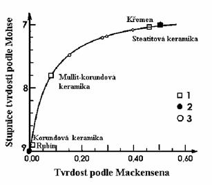
Figure 12 Hardness of the steatite and the
mullite-corundum ceramics according to Szymański (1997); 1- results according
to Budnikov, Kantor (1961 in Budnikov 1964), 2 - Mohs hardness scale; 3 -
various steatite types.
In the
microscopic evaluation of the steaktite ceramics one aims at the evaluation of
the modifications of enstatite, if the growth of its crystals allows it. In the
microstructure of these matters, as small size of the enstatite crystals as
possible, their excellent development and uniform surrounding with a pellucid
glass matter without a perceptible tension are simultaneously required. Fig 8
illustratively shows the different hardness of the steatite, corundum and
mullite-corundum ceramics. Large crystals display the trend towards cracking,
namely under the affect of tension at rapid changes of temperature and
different expansivity of the crystals and the surrounding glass matter. The
glass matter shall isolate individual crystals to prevent their
recrystallization and it stabilizes their undesired transformation to
clinoenstatite.
The
cordierite ceramics is very interesting. Depending on the lenght and degree of
firing, cordierite forms three modifications: high-temperature (a) ,
low-temperature (b) and metastable (m). The a modification of cordierite is of
natural genesis, synteticly it forms by the reaction of suitable
material at a high temperature 1570 - 1750°C (b - modification) and m-cordierite may
form in a slow-cooled glass. Syntetic cordierite called indialite crystallizes
in hexagonal symmetry. Considerable rapid changes of tepmerature resistance
resulting from the low coefficient of temperature expansivity is a typical
property of the cordierite ceramics. Its dielektric properties are inbetween
steatite and porcelain and it has a thin interval of sintering.
α-cordierite is a prevalent mineral in high-quality product. Other
modifications (β, μ) do not practically occur in common products.
α-cordierite characteristics are listed in the encyclopedy of minerals. In
the cordierite ceramics it most frequently forms xenomorphic grains, more
rarely short pseudohexagonal prisms. However, refractions of the cordierite
ceramics are somewhat lower than of natural rocks - usually nmedium =
1.52 - 1.53, D = 0.003 - 0.004, Chm (-). If it is elongated, Chz
(-).
One can
distinguish it from quartz according to D (quartz has somewhat higher
birefringence and is uniaxial). In hypautomorphic up to automorphic crystals a
distinguishing according to the shape of their
sections is possible - squares to rectangles in longitudinal sections and
hexagons in cross sections (watch quartz!) is possible.
In the
cordierite ceramics, cordierite is distinctly perceptible only after firing
over 1300°C, although it forms already from 1200 - 1250°C. Along with the
increasing firing temperature or by its repeating, a recrystallization of
crystals 1 - 2 .10-6m sized to individuals up to 20.10-6m
(at 1400°C) proceeds. Over 1460°C, cordierite decomposes to mullite and a melt.
Mullite forms sheaf-like aggregates, arranged into spherulithes. The aggregates
have square sectionons and they are over 1 mm long and 25 - 50.10-6m
wide. They are composed of needles of mullite. On the contrary, a mullite
glass, devitrificated in the interval of 1460 - 1050°C, contains automorphic
prismatic crystals of α-cordierite, 20 - 50.10-6m long. Some of
them are twinned. At the reaction of MgO-Al2O3-SiO2 components,
cordierite is not the primary compound. Spinel, MgO.Al2O3,
which then reacts with SiO2 to cordierite, forms. In mixtures
composed of soapstone and kaoline, possibly SiO2 and MgO, from
temperatures of 1200 - 1250°C one can observe pseudomorphs after clay minerals
and soapstone, possibly free quartz. The homogenity of the material plays an
important role here. In lower temperatures of firing and in weakly fired
matters relaively sharp separated zones occur in thin sections. They are
composed not only of very fine cordierite, but also protoenstatite, mullitized
clay, free quartz or aggregates of
α-corundum comming from aluminium oxide. The highest level of reacting,
proceeding at the 1300 - 1400°C interval, is displayed by mixtures based on
soapstone and kaoline (at lower temperatures of the stated interval) and based
on kaoline, MgO and SiO2 (at higher temperatures). The ratio usually
is 62 % of caoline + 38 % of soapstone, the firing temperature 1380°C. The
microstrucrure is uniform, dense. Free quartz is not present (unlike in less
quality matters) and cordierite 10. 10-6m sized forms distinct
sheaf-like aggregates here. Individual grains of cordierite are xenomorphic. In
the case of the firing of the material composed of kaoline, magnesite and
ground quartz, a considerable share of 3 - 6.10-6m sized isomorphic
crystals of cordierite occurs, besides small amount of free quartz. Sheaf-like
aggregates cordierite do not occur in this matter, microstructure is
fine confining grained.
The oxide
ceramics includes in fact uniphase molten products of various initial
materials. The absence of glass is a condition of special
physical-chemical properties. A rutile ceramics, various ferrite types based on
geikielite (MgTiO3), armalcolite (Mg,Fe2+)Ti2O5
and other magnesium-titan components
belong into this group of products. Mixtures of geikielite (MgTiO3)
and armalcolite (Mg,Fe2+)Ti2O5 form at the melt crystallization and they may form by solid
phase reactions. Geikielite itself forms as a primery compound only by
the solid phase reaction. Microstructure of these matters is similar to the
microstructure of the steactite ceramics. They contain no or just a minute
amount of glass and prevalent crystallic phase in fine-grained crystals. The
most common magnesium-titan component has the spinel microstructure, it
is isotropic, n = 1.972 and grained. Geikielite is trigonal, distinct cleavable
on [1011], its specific gravity reaches 4.0, hardness 6, metalloidlic lustre.
It is optically uniaxial, Chm(-), ne = 1.95, nw = 2.31, D = 0.36. Armalcolite Mg0.75Fe2+0.25Ti2O5
has a metallic lustre, it is grainy, xenomorphic to hypautomorphic, α = 2.32, γ = 2.39, D =
0.170.
Titanium
dioxide TiO2 forms three modifications: rutile, brookite and
anatase. From the listed minerals only one, namely rutile, is technically
important. Products of pure rutile occur
very rarely. They contain admixtures of Na2O, K2O, Li2O,
Cu2O, BaO, MgO, CaO, SrO, BaO, ZnO, which significantly affect their
dielektric properties. On the contrary, the other trivalent metal (Fe2O3
a Al2O3) admixtures stabilize the dielectric
properties of TiO2.
The most
commonly used and the best surveyed ferroelectric ceramic material is barium
titanate. Its microstructure corresponds to perowskite and it forms by firing
of BaCO3 and TiO2. It forms several modifications:
monoclinic (473°C), rhombic (from 473°C to 550°C), tetragonal (from 550°C to
370 - 673°C) and high-tremperature cubic one.
Optical
constants of bariummetatitanate depend on admixtures as well. Cubic BaO.TiO2
(prepared of pure components) has n = 2.40 - 2.41. Tetragonal BaO.TiO2
(modificated Al2O3, SrO or BeO) have nε =
2.37, nω = 2.50. The cubic high-temperature modification n =
2.46. This modification forms from the tetragonal one.
Ferrites
of spinel microstructures - spinel ceramics. A complete
character of microstructure of these prodacts is to some extent similar to the steatite ceramics. They are
distinct at the prevalence of
crystallic phase. The crystallic phase is often surrounded with minute, often
microscopically unidentifiable, amount of glass. An microscopical assessment
should be aimed at the arrangement, shape, size and granularity of a
prevalent mineral, at the amount and distribution of glass or accessory
minerals and porosity. Optical parameters of the majority of the minerals
occuring in the oxide ceramics are discussed above.
The term
comes from the natural mineral - spinel MgAl2O4, where Al3+
substitues Fe3+ at the formation of ferrite spinelide. Using the
formula of a common spinelide MFe2O4 one is able to
replace M with bivalent cations as Co2+, Fe2+, Ni2+,
Zn2+, Mg2+ and Mn2+. There is the practical
application particularly for ferrites with the spinel type microstructure as:
FeFe2O4, CuFe2O4, MgFe2O4,
Li0,5Fe2,5O4, ZnFe2O4,
CoFe2O4, NiFe2O4.
Ferrites
with a magnetoplumbite (hexagonal) microstructure. Natural magnetoplumbite Pb1.1Fe3+7.7Mn3+2.6Mn2+0.6Ti0.6Al0.4Ca0.1
O19 is represented by only one corresponding form, namely hexaferrite BaFe12O19 in
the group of ferrires. The other identified ferrites considerably differ from
the natural mineral.
In the
M-position, there may be any bivalevt cation represented: Co2+, Fe2+,
Ni2+, Zn2+ and Mn2+. Fe3+ may be
replaced with trivalent cations (Cr3+, Al3+, Sc3+,
In3+, Ga3+, Mn3+ etc.). Analogicly, Ba2+ ions
Ca2+, Sr2+ or Pb2+ ions may be represened
there. Similar ferrites with garnet-like microstructure may exist.
Further, Al2O3,
MgO, BeO, CaO, ZrO2,ThO2, UO2, CeO2
and a series of other oxides first of
all from the lanthanum and actinium-group belong among the oxides of heatproof materials.
High
temperature resistant heatproof materials can be prepared of materials
corresponding to following minerals: corundum (a-Al2O3),
baddeleyite (ZrO2), bromelite (BeO) and other components, without
using high-grade manufacturing technologies, as well as of specially prepared
components.
Bromelite
BeO crystallizes in
hexagonal symmetry, if authomorphic, it is ordinarily prismatic. However in the
oxide ceramics, it is most frequently xenomorphic. It is pellucid, perceptibly
cleavable on {1011}, nε = 1.719, nω = 1.733, D = 0.014, Chm (+).
Thorianite
ThO2
is cubic, in a
thin section, it is red-brown, gray or pellucid, n = 2.20.
One is able
to study the oxide ceramics using thin sections, polished thin sections or
pollished sections. At using the thin sections, it is necessary to make the
sections as thin as possible, aprox. 10 - 20.10-6m thick. In a
series of them, their high hardness is a serious barrier of grinding. Therefore
using of fine boron carbide instead of siliciumcarbide is convenient for
finishing the grinding. For making crystal rims more conspicious, etching the
thin section with HF vapours or acide alkaline sulphates and fluorides or NaOH
for several minutes at relative high temperatures (300 - 350°C) is recommended.
On the contrary, pores come out after filling with a foreign component with a
different refraction ant thus by making the
differences of the refractions more conspicious.
Products of
these type are used in a rocket industry and a nuclear
power-engeneering, where the products must have both heatproof properties and
ability to slow down e.g. neutrons.
A typical
representative of the oxide ceramics is also sintered corundum. In its
crystals, pores are almost always perceptible in a polarization microscope. The
pores are rounded, often mutually connected with thin canals. Their size usualy reaches between 10.10-6m
and 5.10-6m. Unlike in pores of melted corundum, the canals are
neither filled with glass nor crystals were found in them. In another case - in
BeO - the identic orientation of individual pores, which were bounded with
basal, prismatic and pyramidal surfaces, was identified. In sintered corundum,
the pores most frequently occur in relatively large crystals in distinctly
recrystallized matters. No difference between recrystallized and pure Al2O3
fired at high temperatures and admixtures, which distinctly positive affect the
sintering, but at the same time support the recystallization, was found.
Admixtures of MnO, TiO2 and CuO are applicated this way. Extra
ordinary large pores occur in corundum crystals in matters with the most
efficient admixture - a mixture of MnO and TiO2. The distribution of
the crystal pores is not uniform, particularly in matters with sporadic
prsmatic autigenic crystals. Pores are concentrated inside the grains and their
number decreases towards margins.
The absence
of pores close the crystal borders is explained in the connection
with the diffusion of vacant crystal lattice positions. The vacant
positions occur close the pores. The concentration gradient is the condition of
their diffusion to crystal inerfaces, where they disappear. In oter
words, from the crystal interface they difuse to neighbouring pores, fill them
and these gradually get smaller up to disappearing. It leads to the densifying
of individual grains and consequently to shinkage, which manifests even
after reaching the zero absorbability. The proceeding of the shinkage, which is
manifestation of the decreasing of discontinuous porosity and
it corresponds to the increasing of bulk density. Along with
increasing firing temperature, pores inside the crystals get larger. This sort
of pores may work the same as the crystal inetrfaces. Here, both vacant
positions extinct and pores grow larger. The interpretation of the genesis of
the original Ryschkewitsch pores as intercrystal relics was in fact
exeperimentally verified. At the
sintering, the orignal intercrystal pores gradually decrease, as long as the
recrystallization proceeds. Both pores itself and present foreign phases, if
they work as a growth barrier, prevent the recrystallization. As soon as the
total volume of pores decreases below a certain level and the sufficient amount
of a foreign phase is not present, the movement of the crystal inerfaces
towards the centres of their curvature appears and the recrystallization of
corundum begins. Although pores in a close distance to the moving interface
disappear, closing of the pores into the crystal centres, particularly at the
rapid, non-uniform growth of sporadic crystals due to the affect of the
mineralizers, may proceed. In the uniformly coarsened pure Al2O3,
the amount of pores closed in the crystals is in fact lower than in the
intensively recrystallized matters with
the MnO and TiO2 admixtures. In fine-grained matters, the
crystal cavities do not occur at all or are less frequent and reach smaller
extents. This is the an evidence of the fact that pores in these
materials disappeared before the recrystallizetion began or they disappeared
afterwards, sitll during the movement of the crystal interfaces. Bulk density,
which is generally higher than in matters with large crystals, supports it
too.
A
sintered corundum
is microstucturally devideable into several categories. One usually considers a
shape, crystal distribution and the level of
uniform mass-ditribution in a larger space. According to the crystal
shape one distinguishes following types of microstructures: paving, microstructure
formed by rounded grains, confining grained one, formed by long columnar
crystals without a preferential orientation one. The isometric microstructure
may occur in both molten corundum materials and oxide materials. The confining
microstructure occurs only in the oxide matters. According to crystal size we
further devide them into fine-grained (below 10.10-6m) ones and
coarse-grained ones (over 10.10-6m). However, this way of division
may be applicated only in monodispersed matters with crystals of relatively
uniform size. Polydispersed matters contain crystals many times larger than the
average grain-size of matrix.
Microstructure of monodispersed matters may be both isometric and
confining. There may be both molten corundum and oxide matters represented
among them. By deviding the microstructures into four groups (paving,
confining, monodispersed and polydispersed one), it is possible to illustrate
the basical differences between molten corundum and oxide matters.
Microstructure of the molten corundum matters is first of all given by granularity
of the initial material, which stays preserved in coarse grains of fired and
even refired matter. The original granularity of the material only changes in
the smallest particles disappearing at the
exclusion of relatively little increase of medium and large particles.
In the unsintered matter, there are smaller grains of corundum still
perceptible and the average size of the crystal stays approx. the same as in
the initial material. In the sintered matter, the crystal size increases to
aprox 10.10-6m and the fine grains practically disappeare.
The oxide
matters may, unlike the molten corundum matters, display much more significant
microstructural differences. The cause of distinct differences is both the
character of the oxide matter and the sensitivity of the oxide matters to the
affect of the sintering admixtures. We have to consider the sintering
admixtures affect specificly. The affect of some admixtures, e.g. MnO, CuO and
TiO2, leads to the formation of distinct polydispersed
microstructure, even in materials, which, in a pure state, form monodispersed
microstructure even at a complete sintering. Contrawise, the other sintering
admixtures slow the growth, namely both in matter naturaly prone to
polydispersed microstructure and matters with artificial made one. The
artifical microstructure may be caused by e.g. MnO. The affect of MnO is then
canceled. The uniformity of the molten corundum refired matters increases and
they become significantly monodispersive, while the uniformity of the oxide matters
dissapears and they pass into polydispersed ones.
According
to the distribution of crystals in the whole volume of the matter, one
distinguishes uniformly grained and ununiformly grained matters. The ununiformly
grained microstructure forms either at a certain way of formation of the matter
or at faults of preparing of the matter. It ordinarily manifests at casting and
drawing of matters containing anisomertic Al2O3
particles, further at the mixing of the matter, at the admixtures
coarse-granularity and possibly due to the formation of oriented aggregates of
Al2O3 at the matter drainage. In matters containing
anisometric, e.g. lamellar, material particles, the most distinct crystal
orientation appears at the casting. The direct (parallel) arrangement
very well comes through in CPL in the combination with the l - plate. In
this case, prismatic crystals in a suitable combination with an optical
compensor come through in a single shade, e.g. in the blue one and
perpendicular to it in the yellow one. It is possible to assume that the
formation long prismatic corundum crystals is caused by intergrow in oriented
formations of the individual particles. At the drawing of the plastic body the
streaming of the particles and mobility is considerably more difficult than in
a casting mould, so the orientation of the Al2O3 plates
according to basal faces does not manifest so distinctly. The plates tend to
take up a position of as little resistance as possble, considering the
extrusion aperture and in a surface layer they orientate parallel to the axis
of the driven product. The corundum crystal growth proceeds particularly on
the c-axis-direction. The growth in this direction is facilitated by
sliding on basal faces. This corresponds
to the tangential arrangement of prismatic crystals in the driven pipe of the
oxide matter. Considering the fact that these are light walled products, the
orientation is traceable in the entire length of the body. At the semidry
pressing, the conditions for the orientation of the material plates are not so
suitable as at the casting and drawing. Therefore the pressed matters
ordinarily do not display orientation in the entire section of the body. The
shape orientation is traceable particulary in the growth of crystals. In the
cast matter, where the orientation of original Al2O3
plates is the most distinct, the largest prismatic crystals gradually form. On
the contrary, in a not oriented cast matter, the cystals are significantly
smaller of sizes reaching approx. 1/10-1/20 of the large crystals of the cast
matter. Only less ferquently, in the pressed matters, smaller zones composed of
directly oriented crystals, which form so called mosaic-like microstructure may
appear. These nonuniformities are the best identifiable using the gypsum plate
in CPL as well. An explanation of the orientation in the pressed matters is not
completely distinct. Most likely, the orientation of particles formed in
prepared matter in the wet environment plays a role here (this sort of
orientation is known e.g. from the kaoline drainage). A sliding on anisometric
particles, possibly certain „streaming of matter“ at pressing may also be
considered. However, the ununiform, particulary directly oriented
microstructure always worsens the required properties.
Technolithology
is inter-disciplinary branch standing between material engineering and
geological disciplines. Geological disciplines (mineralogy, petrology, and
geochemistry) stand ahead in technolithe research. It has become clear that
with technolithes, a new research scope for technical disciplines (particularly
for material engineering section) has emerged. Recently, basic research
perspectives have been determined for geological science disciplines with some minor
successful issues (Rovnaníková et
al 1999, Gregerová 2000, 2000b, 2000a,
2000c, Gregerová et al 2000, Gregerová,
Pospíšil 2000). The issues include research of rule-based relationships between
ettringite- thaumasite formation and alkali silica gels in concrete
construction exposed to specific environmental conditions. Using microscopy
methods, RTG, DTA, electron microscopy, and microanalysis, certain rule-based
relationships among stable, metastable, and secondary minerals in building
construction cements have been revealed (Gregerová 2000a, 2000c, Gregerová,
Pospíšil 2000a, Gregerová, Rovnaníková 2002 Witzany et al. 2002).
Technolithe
minerals require specific approach of mineralogists. The crystals form solid
solutions of several isomorphic miscible components and feature multiple
modifications with unknown relationships.
Special
alloys, superconductors, and monocrystalline layers represent an interesting
group of technolithes. Microscopic
research may include for example inclusions in alloys, monocrystals, glass, and
ceramic products. Mineral fibre study information (for example, whiskers,
endless fibres) may be significant too.
Technolithology
methods can be also used to inspect historic materials in petroarchaeological
study (Gregerová, Kristová 1995, Gregerová Hložek 2000, 2002). Prospective
research types include study of inorganic phosphate fertilizers.
It is
obvious that the technolithology may affect many disciplines in several ways
(see Figure 10).
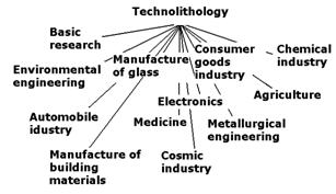
Figure 10
Position of technolithology and relationships with industry branches.
It is worth
stating that technolithology is not the only perspective option for
mineralogists, petrologists, and geochemists. The other trends include
biomaterial/biomineralization study.
The results
have been obtained on a long-term basis in GACR projects No. 103/00/0607 and
103/02/0990.
1. Bartuška, M. (1964)“ Mikroskopie minerálů.- Skripta ČVUT. Praha.
2. Bartuška M. (1987): Technická mineralogie.- Skripta VŠCHT. Praha
3. Berry, L. G., Mason, B. (1959): Mineralogy, concepts, descriptions, determinations.- W.H. Freeman and Co, San Francisco.
4. Bielankin, D.S., Ivanov, B.V., Lapin, V. V. (1957): Petrografia kamieni sztucznych.-Wyd. Geol., Warszawa.
5. Cohen, M. (ed.) (1980): Materials Science and Dist Engineering – Its Evaluation, Practice and Prospects.- Elsevier, Amsterdam.
6. Deer, W. A., Howie, R. A. and Zussman, J. (1992): Rock-forming Minerals - An introduction to the rock-forming minerals 2nd. – ed. Longman, 687 str. Essex.
7. Deer,
W. A, Howie, R. A. and Zussman, J. (1997- 2001): Rock-forming Minerals Series:
8. Volume 1A: Orthosilicates (second
edition)
9. Volume 1B: Disilicates & ring
silicates (second edition)
10. Volume 2A: Single-chain silicates
(second edition)
11. Volume 2B: Double-chain silicates
(second edition)
12. Volume 4A: Framework silicates:
Feldspars (second edition).
13. The Geological Society. London.
14. Ginsberg A.S. (1951): Eksperymentalnaja petrografija.- Nauka. Leningrad.
15. Gregerová, M. (1996): Petrografie technických hmot.- Učební texty, PřF MU v Brně.
16. Gregerová, M. (2000): Petrografie technických hmot.- Habilitační práce, nepublikováno, VUT Brno.
17. Gregerová, M. (2000a): Petrografické rozbory malt, jejich relativní datování podle stupně degradace pojiva.- Geologické výzkumy na Moravě a ve Slezsku v roce 1999. ISSN 1212-6209, 2000, vol. VII, no. 1, s. 149-151.
18. Gregerová, M.(2000b): Uplatnění digitální fotografie v aplikované mineralogii a petrografii.- In Mikroskopie 2000. Vyd. 1. Praha : ČVUT Praha, 2000. Mikroskopie 2000, ISBN 80-01-02244-7, s. 13-15.
19. Gregerová, M. (2000c): Vzdušné malty historických staveb, jejich identifikace, příčiny degradace a návrh sanace.- Geologické výzkumy na Moravě a ve Slezsku v roce 1999. ISSN 1212-6209, 2000, vol. VII, no. 1, s. 152-154.
20. Gregerová, M., Fojt, B., Vávra V. (2002): Mikroskopie horninotvorných a technických minerálů.- Moravské zemské muzeum – Přírodovědecká fakulta MU v Brně. 325 str. ISBN 80-7028-195-2.
21. Gregerová, M., Hložek, M. (2000): Technologické posouzení keramické produkce na sídlišti s vypíchanou keramikou v Pavlově.- In Sborník Miroslavu Buchvaldkovi. Most: Ústav archeologické památkové péče severozápadních Čech v Mostě, 2000. ISBN 80-901828-6-8, s. 81-86.
22. Gregerová, M., Hložek, M. (2002): Stanovení společných technologických znaků dvou částí antropomorfní nádoby lengyelské kultury z Těšetic-Kyjovic. - Nitra : Archeologický ústav SAV, 2002. 430 s. Archeaologica Slovaca Monographiae, Tomus.IV. ISBN 80-88709-57-1.
23. Gregerová, M., Kristová, L. (1995): Probleme der Interpretation der differenz-thermischen Analysen der Graphittonkeramik.- II Internationale tagungen in Mikulčice: Slawische Keramik in Mitteleuropa von 8. bis zum 11. Jahrhundert - Terminologie und Beschreibung, Spisy Archeologického ústavu AV ČR Brno, 4, 213-223. Brno.
24. Gregerová, M., Pospíšil, P. (2000): Microscopic methods applied to study of historical mortars and plasters.- In Proceedings of the 8th Euroseminar on Microscopy Applied to Buildings Materials. Vyd. 1. Atheny : Atheny, 2001. s. 353-358.
25. Gregerová, M., Pospíšil, P. (2000a): Možnosti digitální rastrové technologie pro studium degradačních procesů. In Mikroskopie 2000. Vyd. 1. Praha : ČVUT Praha, 2000. Mikroskopie, ISBN 80-01-02244-7, s. 25-30.
26. Gregerová, M., Pospíšil, P., Rovnaníková, P. (2000): Identification of the Roman cements in Bohemian and Moravian Historical Buildings. In 5th International congress on restoration of architectural heritage Firenze 2000. Vyd. 1. Florencie, Itálie : University of Florence, 2000. s. 1527-1536.
27. Gregerová, M., Rovnaníková, P. (2002): Tvorba výkvětů na povrchu betonu. In VII. Vedecká konferencia s medzinárodnou účasťou. Zborník prednášok 10. sekcia: Stavebné materiály. Košice : Technická univerzita v Košiciach. Stavebná fakulta, 2002. Zborník príspevkou zo VII. Vedeckej konferencie, ISBN 80-70-99-816-4, s. 185-189.
28. Gregerová, M., Sulovský, P. (1994): Možnosti využití elektronové mikroskopie a mikroanalýzy.- Geol. výzk. Mor. Slez. v r. 1993, 103-104. Brno.
29. Hejtman, B.(1956):Všeobecná petrografie vyvřelých hornin. 376 s. Nakladatelství CSAV, Praha.
30. Hornbogen, E. (1983): Metall, 37(5), 472 – 475.
31. Huang, W.T. (1962): Petrology.- McGrow-Hill Book. New York.
32. Kohl, W., H. (1977): Mat. Electron., 3 (19). 45-46.
33. Konta J. (1982): Keramické a sklářské suroviny.- UK Praha.
34. Matoušek, M., Drochytka, R. (1998): Atmosférická koroze betonů.- IKAS. 161 str. Praha.
35. Rovnaníková, P., Gregerová, M., Krmíčková, N. (1999): Složení a náhrada omítek historických staveb.- In XI. Mezinárodní końference, 18.-20. října 1999 - Vysoké učení technické, Fakulta stavební, Sborník příspěvků. Vyd. 1. Brno : VUT Brno, 1999. s. 157-160-4.
36. Ryshkevitch, E. (1960): Oxide Ceramics.- Akad. Press. New York.
37. Vražičová, J.,(2002): Reakční mechanismus tvorby pojiva na bázi fosforečnanu hořečnato-amonného, Sborník příspěvků ze IV. semináře Pokroky v anorganické chemii, MU v Brně, 2002, s. 68-69, ISBN 80-210-2951-X.
38. Szymański, A.(1997): Mineralogia techniczna.- Wydawnictvo Naukowe PWN. 459 str. Warszawa. ISBN 83-01-12208-0.
39. Witzany, J., Gregerová, M., Pospíšil, P.,
Wasserbauer, R., Hruška, A., Cikrle, P. (2002):
Projekt Karlova mostu. I. etapa - diskuze.- Projekt měsíčník pro stavebnictví a
interiéry. ISSN 1211-9490, 2002, vol. VI, s. 27-35.